3
©
2019 Columbus McKinnon Industrial Products GmbH
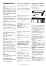
Prüfung der Bremse
Bei Auffälligkeiten (z.B. defekten Friktionsscheiben) ist sofort mit dem Hersteller
Rücksprache zu halten. Alle Bauteile der Bremse sind auf Verschleiß, Beschädigungen,
Verfärbungen durch Überhitzung und Funktion hin zu überprüfen.
Friktionsscheiben unbedingt frei von Fett, Öl, Wasser und Schmutz halten. Die
Verklebung der Friktionsscheiben ist zu überprüfen.
Austausch der Handkette
• Als Hilfsmittel wird ein offenes Lastkettenglied benötigt. Es kann durch
Herausschleifen eines Stückes aus einem vorhandenen Kettenglied gleicher Dimension
hergestellt werden. Dabei muss die Länge des herausgetrennten Stückes mindestens
der Kettengliedstärke entsprechen.
• Alte Handkette (bevorzugt am Verbindungsglied) öffnen und das offene Kettenglied in
das lose Handkettenende hängen, welches noch "vor" dem Handkettenrad liegt.
• Die neue Handkette ist ebenfalls in das offene Kettenglied einzuhängen und durch die
Kettenführungen und über das Handkettenrad zu ziehen.
• Kette nicht verdreht einbauen. Die Schweißnähte müssen nach außen weisen.
• Die alte Handkette inklusive dem offenen Verbindungsglied von der neuen Handkette
trennen und die beiden losen Enden der neuen Handkette mittels einem neuen
Handkettenverbindungsglied verbinden.
Reparaturen dürfen nur von autorisierten Fachwerkstätten, die Original Yale
Ersatzteile verwenden, durchgeführt werden.
Nach einer erfolgten Reparatur sowie nach längerer Standzeit ist das Hebezeug vor der
Wiederinbetriebnahme erneut zu prüfen.
Die Prüfungen sind vom Betreiber zu veranlassen.
T
RANSPORT
,
L
AGERUNG
,
A
USSERBETRIEBNAHME UND
E
NTSORGUNG
Beim Transport des Gerätes sind folgende Punkte zu beachten:
• Gerät nicht stürzen oder werfen, immer vorsichtig absetzen.
• Hand- und Lastkette sind so zu transportieren, dass sie sich nicht verknoten können
und sich keine Schlaufen bilden können.
• Geeignete Transportmittel verwenden. Diese richten sich nach den örtlichen
Gegebenheiten.
Bei der Lagerung oder der vorübergehenden Außerbetriebnahme des Gerätes
sind folgende Punkte zu beachten:
• Das Gerät an einem sauberen und trockenen Ort lagern.
• Das Gerät inkl. aller Anbauteile vor Verschmutzung, Feuchtigkeit und Schäden durch
eine geeignete Abdeckung schützen.
• Haken vor Korrosion schützen.
• Die Ketten sind mit einem leichten Schmierfilm zu überziehen.
• Da bei Temperaturen unter 0 °C die Bremsscheiben vereisen können, sollte das Gerät
mit geschlossener Bremse gelagert werden. Hierzu das Handkettenrad bei
gleichzeitigem Festhalten des Laststranges im Uhrzeigersinn drehen.
• Soll das Gerät nach der Außerbetriebnahme wieder zum Einsatz kommen, ist es
zuvor einer erneuten Prüfung durch eine befähigte Person zu unterziehen.
Entsorgung
Nach Außerbetriebnahme sind die Teile des Gerätes entsprechend den gesetzlichen
Bestimmungen der Wiederverwertung zuzuführen bzw. zu entsorgen.
Weitere Informationen und Betriebsanleitungen zum Download sind unter
www.cmco.eu zu finden!
EN - Translated Operating Instructions (Also
applicable for special versions)
I
NTRODUCTION
Products of CMCO Industrial Products GmbH have been built in accordance with the
state-of-the-art and generally accepted engineering standards. Nonetheless, incorrect
handling when using the products may cause dangers to life and limb of the user or
third parties and/or damage to the hoist or other property.
The operating company is responsible for the proper and professional instruction of the
operating personnel. For this purpose, all operators must read these operating
instructions carefully prior to the initial operation.
These operating instructions are intended to acquaint the user with the product and
enable him to use it to the full extent of its intended capabilities. The operating
instructions contain important information on how to operate the product in a safe,
correct and economic way. Acting in accordance with these instructions helps to avoid
dangers, reduce repair costs and downtimes and to increase the reliability and lifetime
of the product. The operating instructions must always be available at the place where
the product is operated. Apart from the operating instructions and the accident
prevention act valid for the respective country and area where the product is used, the
commonly accepted regulations for safe and professional work must also be adhered
to.
The personnel responsible for operation, maintenance or repair of the product must
read, understand and follow these operating instructions.
The indicated protective measures will only provide the necessary safety, if the product
is operated correctly and installed and/or maintained according to the instructions. The
operating company is committed to ensure safe and trouble-free operation of the
product.
C
ORRECT
O
PERATION
The unit is used for vertical lifting and lowering of loads up to the indicated max. load
capacity. In combination with trolleys, loads can also be moved horizontally.
ATTENTION: The unit may be used only in situations in which the load carrying
capacity of the device and/or the supporting structure does not change with the
load position.
Any different or exceeding use is considered incorrect. Columbus McKinnon Industrial
Products GmbH will not accept any liability for damage resulting from such use. The
risk is borne by the user or operating company alone.
The load capacity indicated on the unit is the maximum working load limit (WLL) that
may be attached.
If the hoist is to be used for frequent lowering from large heights or in indexed
operation, first consult the manufacturer for advice because of possible overheating.
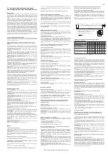
The top hook and the load hook of the unit must be in a vertical line above the load
centre of gravity (S) when the load is lifted, in order to avoid load sway during the lifting
process.
The selection and calculation of the appropriate supporting structure are the
responsibility of the operating company.
The attachment point and its supporting structure must be designed for the maximum
loads to be expected (deadweight of the unit + load capacity).
The operator must ensure that the hoist is suspended in a manner that makes it
possible to operate the unit without exposing himself or other personnel to danger by
the unit itself, the suspension or the load.
The operator may start moving the load only after it has been attached correctly and all
persons are clear of the danger zone.
Do not allow personnel to stay or pass under a suspended load.
A lifted or clamped load must not be left unattended or remain lifted or clamped for a
longer period of time.
The hoist may be used at ambient temperatures between –10° and +50°C. Consult the
manufacturer in the case of extreme working conditions.
ATTENTION: Before use at ambient temperatures of less than 0°C, check the
brake for freezing by lifting and lowering a small load 2 - 3 times.
Prior to operation of the hoist in special atmospheres (high humidity, salty, caustic,
alkaline) or handling hazardous goods (e.g. molten compounds, radioactive materials),
consult the manufacturer for advice.
Always transport the load in the horizontal direction slowly, carefully and close to the
ground.
When the unit is not in use, position the suspension (e.g. bottom block, hook) above
normal head height, if possible.
For attaching a load, only approved and certified lifting tackle must be used.
Correct operation involves compliance with the operating instructions and in addition
also compliance with the maintenance instructions.
In case of functional defects or abnormal operating noise, stop using the hoist
immediately.
I
NCORRECT
O
PERATION
(List not complete)
Do not exceed the rated load capacity (WLL) of the unit and/or the suspension and the
supporting structure.
The unit must not be used for pulling free fixed loads. It is also prohibited to allow loads
to drop when the chain is in a slack condition (danger of chain breakage).
Removing or covering labels (e.g. by adhesive labels), warning information signs or the
identity plate is prohibited.
When transporting loads ensure that the load does not swing or come into contact with
other objects.
The load must not be moved into areas which are not visible to the operator. If
necessary, he must ensure he is given help.
Driving the unit with a motor is not allowed.
The unit must never be operated with more than the power of a person.
Welding on hook and load chain is strictly forbidden. The load chain must never be
used as a ground connection during welding.
Side pull, i. e. side loading of either the housing or the bottom block is forbidden.
The load chain must not be used as a chain sling.
A unit changed without consulting the manufacturer must not be used.
Do not use the hoist for the transportation of people.
Do not knot the load chain or connect it by using pins, bolts, screw drivers or similar. Do
not repair load chains installed in the hoist.
Removing the safety latches from top and/or load hooks is forbidden.
Never attach the load to the tip of the hook. The lifting tackle must always be seated in
the saddle of the hook.
Do not use the chain stop as an operational limit device.
Turning of loads under normal operating conditions is not allowed, as the bottom blocks
of the hoists are not designed for this purpose. If loads must be turned in normal
operation, an anti-twist swivel must be used or the manufacturer must be consulted.
Only one load lifting attachment may be suspended in the load hook of the hoist.
Never reach into moving parts.
Do not allow the unit to fall from a large height. Always place it properly on the ground.
The unit must not be used in potentially explosive atmospheres.
A
SSEMBLY
Inspection of the attachment point
The attachment point for the hoist must be selected so that the supporting structure to
which it is to be fitted has sufficient stability and to ensure that the expected forces can
be safely absorbed.
The unit must align freely also under load in order to avoid impermissible additional
loading.
The selection and calculation of the appropriate supporting structure are the
responsibility of the operating company.
Shorten or extend the hand chain
Adjust the length of the hand chain so that the distance of the lower end to the floor is
between 500 – 1000 mm.
NOTE: For safety reasons, hand chain links may only be used once.
• Look for the non-welded link of the hand chain, bend to open and discard it.
• Shorten or extend the chain to the required length.
ATTENTION: Always remove or add an even number of chain links.
• Use a new link to close the loose chain ends by bending it (for extending the hand
chain, two new chain links are required).
ATTENTION: Make sure that hand chains are not twisted while they are fitted.
b
h
a
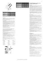
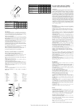
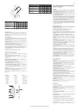
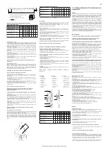
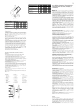
Hakenmaße / Hook dimensions / Dimensions du crochet
VS
III
0,25/1
0,5/1
1/1
1,5/1
2/1
2/2
3/1
3/2
5/2
Hakenöffnungsmaß / Hook opening
Ouverture du crochet
a
nom.
a
max.
[mm]
[mm]
26,0
28,6
30,0
33,0
33,0
36,3
36,0
39,6
40,0
44,0
40,0
44,0
46,0
50,6
46,0
50,6
54,0
59,4
Maß Hakenbreite / Hook width
Largeur du crochet
b
nom.
b
min.
[mm]
[mm]
11,0
10,5
17,0
16,2
19,0
18,1
22,0
20,9
26,0
24,7
26,0
24,7
30,0
28,5
30,0
28,5
40,0
38,0
Maß Hakendicke / Hook height
Hauteur du crochet
h
nom.
h
min.
[mm]
[mm]
12,0
11,4
21,0
20,0
27,0
25,7
33,0
31,4
35,0
33,3
35,0
33,3
43,0
40,9
43,0
40,9
47,0
44,7
Tab. 3
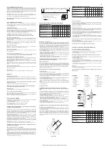
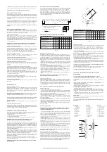
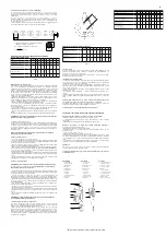
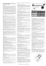
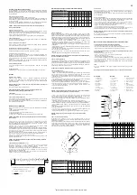
Beschreibung
1 Traghaken mit
Sicherheitsbügel
2 Handraddeckel
3 Lastkette
4 Unterflasche
5 Getriebedeckel
6 Handkette
7 Lasthaken
mit Sicherheitsbügel
8 Kettenanker
9 Handrad
Description
1 Top hook with
safety latch
2 Hand wheel cover
3 Load chain
4 Bottom block
5 Gear cover
6 Hand chain
7 Load hook
with safety latch
8 Chain anchorage
9 Handwheel
Description
1 Crochet de suspension,
linguet de sécurité
2 Capot de protection
3 Chaîne de charge
4 Moufle
5 Carter engrenage
6 Chaîne de manoeuvre
7 Crochet de charge,
linguet de sécurité
8 Arrêt de chaîne
9 Volant de manouvre
2
3
4
9
6
7
8
1
5
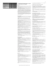
VS
III
0,25/1 0,5/1
1/1
1,5/1
2/1
2/2
3/1
3/2
5/2
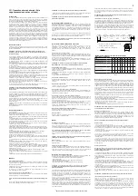
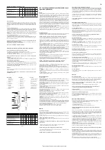
Tragfähigkeit / Capacity / Capacité
[kg]
250
500
1.000
1.500
2.000 2.000
3.000
3.000
5.000
Anzahl Kettenstränge / Number of chain falls / Nombre de brins
1
1
1
1
1
2
1
2
2
Kettenabmessung d x p
n
/ Chain dimensions d x p
n
Dimensions de la chaîne d x p
n
[mm]
4 x 12
5 x 15 6 x 18 8 x 24 8 x 24 6 x 18 10 x 30 8 x 24 10 x 30
Hub je 1 m Abhaspelung der Handkette
Lift per 1 m hand chain overhaul
Course pour 1 m de chaîne de manoeuvre
[mm]
50,0
33,0
23,0
17,0
18,0
12,0
12,0
9,0
6,0
Hubkraft bei Nennlast
Hand pull at rated load
Effort sur la chaîne de manoeuvre
[daN]
20,0
21,0
28,0
30,0
33,0
29,0
37,0
31,0
35,0
Gewicht bei Normalhub
Net weight at standard lift
Poids net en course standard
[kg]
3,9
9,0
12,2
17,5
19,3
18,2
35,0
29,0
41,0
Tab. 1


