


9
P/N 192047138 Rev AA November 2017
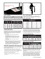
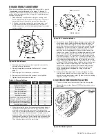
Figure 8 - Nameplate
Note
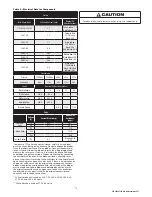
In this manual, nominal voltages are used when referring to power
supply systems. However, with no modification, the Shopstar
Hoist will operate on a range of voltages as indicated below:
Table 2 - Nominal Voltage
NOMINAL
VOLTAGE
VOLTAGE
RANGE
HERTZ
TRADITIONAL
CONTACTOR
PRINTED
CIRCUIT BOARD
230
208-240
60
AVAILABLE
AVAILABLE
460
440-480
60
AVAILABLE
NOT AVAILABLE
220
200-240
50
AVAILABLE
AVAILABLE
380
365-395
50
AVAILABLE
AVAILABLE
415
400-415
50
AVAILABLE
AVAILABLE
430
415-430
50
AVAILABLE
NOT AVAILABLE
575
550-600
60
AVAILABLE
NOT AVAILABLE
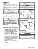
THREE PHASE HOISTS
Since the motor in a three phase hoist can rotate in either direction,
depending on the manner in which it is connected to the power
supply, the direction of hook movement must be checked during
the original installation and each time hoist is moved to a new
location as follows:
1. Move the manual disconnect switch handle to the
“OFF” position.
2. Connect the BROWN, GREY AND BLACK wires of hoist
power cord to load side of disconnect switch. Connect
the GREEN-YELLOW wire of hoist power cord to power
supply ground.
3. Move the manual disconnect switch handle to the
“ON” position.
4. Depress the (up) control. If the hook moves in the up direction,
the hoist is ready for operation. If the hook lowers, move
the disconnect switch handle to the “OFF” position and
interchange the BLACK and BROWN leads at the disconnect
switch. Move the disconnect switch handle to the “ON”
position and the hoist is now ready for operation.
CHECKING FOR ADEQUATE VOLTAGE AT HOIST
The hoist must be supplied with adequate electrical power for proper
operation and to reduce problems that may result from insufficient
power (low voltage). These include:
• Noisy hoist operation due to brake and/or contactor chatter.
• Heating of the hoist motor and other internal components as well
as heating of wires and connectors in the circuit feeding the hoist.
• Failure of the hoist to lift the load due to motor stalling.
• Blowing fuses or tripping circuit breakers.
• Dimming of lights or slowing of motors connected to the
same circuit.
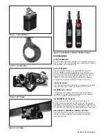
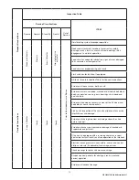
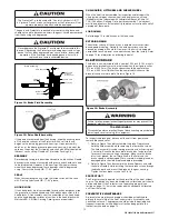
UPPER HOOK
LOOSE END OF CHAIN
CHAIN STOP
LOWER HOOK
POWER
CORD
CONTROL STATION
Figure 9 - Hoist Components
For proper operation and to avoid these low voltage problems,
voltage (measured at end of the power cord while lifting rated load)
should be as the following chart indicates.
Table 3 - Start-up Voltage
NOMINAL MINIMUM * MIN. VOLTAGE
POWER OPERATING AT INSTANT
SUPPLY VOLTAGE OF START
115-1-50/60
108
220-1-50
198
208-3-60
187
220-3-50
198
230-3-60
207
380-3-50
365
415-3-50
399
460-3-60
414
575-3-60
518
*The drop in voltage upon energizing the hoist should not be below the value listed.
Low voltage can also be caused by using an undersize extension
cord to supply power to the hoist. The following charts should be
used to determine the size wires in the extension cord in order to
minimize the voltage drop between the power source and the hoist.
115-1-50/60 units with contactor, 220-1-50 units and three phase
units (hoists with black control station)
Table 4a - Adequate Power Supply
MAXIMUM LENGTH OF EXTENSION CORD
Wire Size
Single Phase Hoist
Three Phase Hoist
#16 A.W.G.
135 ft (40m)
245 ft (73m)
#14 A.W.G.
220 ft (66m)
395 ft (120m)
#12 A.W.G.
354 ft (107m)
630 ft (192m)
115-1-50/60 units without contactor (hoists with orange control station)
Table 4b - Adequate Power Supply
LENGTH OF CONTROL
CORD ft(m)
MAXIMUM LENGTH OF EXTENSION CORD
BASED ON SIZE OF WIRE
#16 AWG
#14 AWG
#12 AWG
1.0 to 10.0 (0.3 to 3.0)
105ft (32m)
170ft (51m)
270ft (82m)
11.1 to 20.0 (3.1 to 6.0)
75ft (22m)
120ft (36m)
190ft (58m)
21.1 to 30.0 (6.1 to 9.0)
45ft (14m)
70ft (21m)
110ft (33m)
31.1 to 40.0 (9.1 to 12.0)
15ft (4.5m)
20ft (6m)
35ft (11m)
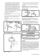
After the hoist is suspended from its support and you have made
sure the power supply complies with the above, the hoist is ready
for operation.
On the Double units, cut and discard the ties used to hold the two
strands of chain together. With no load on the lower hook, depress
the UP button in the control station and raise the lower hook
until it is about 2 feet below the bottom of the hoist. Check both
strands of chains for twists. Twists occur if the lower hook block
has been capsized between the strands of chain during packing,
shipment and/or handling. Reverse the capsize to remove twists.


