CM Shopstar Скачать руководство пользователя страница 23

23

P/N 192047138 Rev AA November 2017

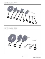
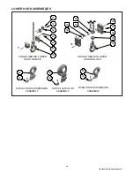
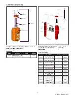
DISASSEMBLY-ASSEMBLY

When disassembling and assembling the Shopstar Hoist, refer to 

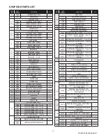
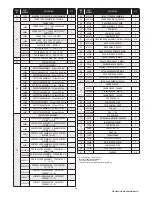
 the exploded view and the parts list on pages 15 through 18.  

These show the proper relationship of the parts, the names of the 

parts and the required quantities of the parts. In addition, please 

observe the following:

1.  Needle bearings are pressed into the gear housing, main  

frame, liftwheel and lower sheave wheel. Unless they are to  

be replaced, do not attempt to remove these bearings.

2.  A liftwheel seal is pressed into the main frame and a seal  

is pressed into the end of the liftwheel shaft. Be careful  

that these seals are not cut or damaged during disassembly  

and reassembly.

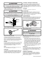
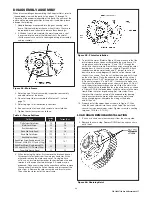
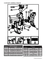
Figure 24 - Main Frame

3.  Refer to page 13 for disassembly, inspection, reassembly  

and adjustment of the brake.

4.  Do not attempt to disassemble the Protector™ - refer to  

page 13.

5.  Refer to page 14 for lubrication instructions.

6.  See next section for load chain removal and installation.

7.  Tighten the various screws as follows:

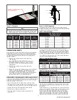
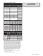
Table 6 - Torque Settings

Part Name

Seating 

lb·in

Torque (N·m)

Pin Retainer Plate Screw

25

2.8

Motor Cover Screw

25

2.8

Gear Housing Screw

25

2.8

Brake End Cover Screw

25

2.8

Dead End Plate Screw

125

14.1

Hook Retainer Screw

10

1.1

Hook Block Screw, Double-reeved, 500, 

600 and 1,000 lb (226, 272 and 453 kg) 

125

14.1

Hook Block Screw, Single-reeved, 250, 

300 and 500 lb (113, 136 and 226 kg)

50

5.6

Power Cord Ground Screw

20

2.2

8.  When removing the stator , first remove the brake end cover. 

Disconnect stator leads from the wiring or contactor. At the 

other end, remove the motor end cover. On single phase 

units, use an insulated screw driver to short between the bare 

terminals of the capacitor to discharge it. A spark may be 

produced. Disconnect wiring to the capacitor and then remove 

the capacitor. Remove the cut-out device and disconnect the 

wires from it. Remove the rotor assembly and thrust washer. 

Then slide the stator out of the main frame.

Pin Retainer Plate

Wire
Slot

Figure 25 - Stator Installation

9.  To install the stator, (Refer to Figure 24) and make sure that the 

pin retainer plate has been assembled to the main frame. On 

single phase units slide jumpers “2” and “CAP” through the 

wire slot in the main frame. Route these wires around the rotor 

bearing boss in the main frame as shown in Figure 25. Attach 

the brown and blue stator leads and “2” jumper to cut-out 

device (refer to wiring diagram). Slide the cut-out device into 

the cavity as shown. Push the cut-out device down until it sets 

on the main frame. Place the capacitor on top of the cut-out 

device and attach “CAP” jumper and the yellow stator lead to 

it. Re-route jumpers “2” and “CAP”, if necessary to make sure 

they clear the rotor bearing boss as shown in Figure 25. On all 

units slide stator leads through wire slot. Align the slots in the 

stator shell with the threaded holes in the main frame, as shown 

in Figure 24. With the leads down, slide the stator into the main 

frame. Slide the rotor, large bearing first, into stator. Place  

the rotor thrust washer on top of the exposed rotor bearing  

and then assemble the motor end cover to the main frame.  

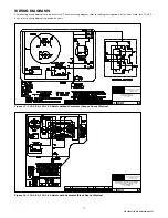
Using wiring diagram, complete the wiring at the brake  

end of the unit.

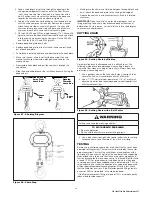
10.  Properly install the upper hook as shown in Figure 27, then 

slide the hook retainer into the cavity on top of the hoist and 

secure it using hook retainer screw. Tighten screw to a seating 

torque of 10 in. lbs. (1.1 NM).

LOAD CHAIN REMOVAL/INSTALLATION

1.  If unit has a chain container, remove it from the chain guide.

2.  Remove the chain stop. Depress DOWN button and run chain 

out of hoist.

Figure 26: Chaining Hoist

Содержание Shopstar

Страница 1: ...sed if proper instructions and warnings are not followed Before using this hoist each operator should become thoroughly familiar with all warnings instructions and recommendations in this manual Retain this manual for future reference and use Forward this manual to the hoist operator Failure to operate equipment as directed in manual may cause injury Columbus McKinnon Corporation 205 Crosspoint Pa...

Страница 2: ...puesto y centros de servicio situados estratégicamente en Estados Unidos y Canadá Estas instalaciones se han seleccionado en base a su capacidad demostrada en la reparación de equipos y suminstro de piezas de repuesto de forma rápida y eficaz Para obtener la dirección del almacén de piezas de repuesto o del centro de servicio más cercano llame al teléfono 800 888 0985 Fax 716 689 5644 sólo en Esta...

Страница 3: ... brake function by tensioning the hoist prior to each lift operation c Use hook latches Latches are to retain slings chains etc under slack conditions only d Make sure the hook latches are closed and not supporting any parts of the load e Make sure the load is free to move and will clear all obstructions f Avoid swinging the load or hook g Make sure hook travel is in the same direction as shown on...

Страница 4: ...of your loads Then match them The application the size and type of load the attachments to be used and the period of use must also be taken into consideration in selecting the right hoist for the job Remember the hoist was designed to ease our burden and carelessness not only endangers the operator but in many cases a valuable load DO NOT OPERATE DAMAGED OR MALFUNCTIONING HOIST DO NOT OPERATE WITH...

Страница 5: ...Inspection 13 Hook Replacement Criteria 13 Inspecting The Load Chain 13 Lubrication 14 Electric Brake 15 TROUBLESHOOTING General 16 ELECTRICAL DATA Open or Short Circuit in Electrical Components 17 WIRING General 19 DISASSEMBLY ASSEMBLY General 23 Load Chain Removal Installation 23 Cutting Chain 24 Testing 24 Repair Parts List 25 ORDERING INSTRUCTIONS General 25 RECOMMENDED SPARE PARTS General 25 ...

Страница 6: ...efore using this hoist each operator should become thoroughly familiar with all warnings instructions and recommendations in this manual Retain this manual for future reference and use Forward this manual to the hoist operator Failure to operate the equipment as directed in the manual may cause injury Before putting hoist into service fill in the information below Refer to the hoist identification...

Страница 7: ...s are shipped separately and can be furnished for units already in service LATCHLOK HOOKS CM s Latchlok hooks are available Figure 2 to replace the standard upper and lower hooks used on the Shopstar Electric Hoists CM SERIES 632 TROLLEY This lightweight yet rugged manual push type trolley Figure 3 is designed to fit a wide range of monorail beams and negotiate tight curves Provides mobility of yo...

Страница 8: ...15 amps and it should have 16 AWG or larger wiring 2 Be in accordance with the National Electrical Code ANSI NFPA 70 and applicable National State and Local Codes 3 Effectively ground the hoist in accordance with National Electrical Code and other applicable codes Proper grounding provides a path of least resistance for electric current to reduce the risk of electric shock The power cord of the ho...

Страница 9: ...imming of lights or slowing of motors connected to the same circuit UPPER HOOK LOOSE END OF CHAIN CHAIN STOP LOWER HOOK POWER CORD CONTROL STATION Figure 9 Hoist Components For proper operation and to avoid these low voltage problems voltage measured at end of the power cord while lifting rated load should be as the following chart indicates Table 3 Start up Voltage NOMINAL MINIMUM MIN VOLTAGE POW...

Страница 10: ...is depressed and it will continue to lower the load until the control push button is released As a result the direction must not be reversed quickly plug reversed There are no electrical switches to stop the operation of the hoist at the upper and lower limits of lift As a result it is necessary to release the push button in the control station to stop the hoist components from damage However cont...

Страница 11: ...n load hook is not centered overhoist DO NOT Permit load hook block to contact hoist frame or chain container DO Replace damaged or malfunctioning hook latch DO Keep load chain well oiled DO Read ASME B30 16 Safety Code for Hoist and appropriate operating instructions MAINTENANCE INSPECTION To maintain continuous and satisfactory operation a regular inspection procedure must be initiated to replac...

Страница 12: ...ble for frequent inspections Evidence of loose screws bolts or nuts Evidence of worn corroded cracked or distorted hook block body suspension screws gears bearings chain dead end and chain pin Evidence of damage or excessive wear of the lift wheel and hook block sheave chain pockets Link by link inspection of the chain for evidence of excessive interlink wear and damage Evidence of chain guide wea...

Страница 13: ...ed alterations such as drilling machining grinding or other modifications INSPECTING THE LOAD CHAIN The chain must be inspected at regular intervals with a minimum of once annually As the frequency of use increases the time Intervals between inspections must be reduced During inspection the chain link must be examined along their entire length including the hidden parts If the lifting equipment is...

Страница 14: ...ry Keep it clean and lubricate at regular intervals with Lubriplate Bar and Chain Oil 10 R Fiske Bros Refining Co or equal lubricant Normally weekly lubrication and cleaning is satisfactory but under hot and dirty conditions it may be necessary to clean the chain at least once a day and lubricate it several times between cleaning When lubricating the chain apply sufficient lubricant to obtain natu...

Страница 15: ...ubricant must be applied in sufficient quantity to obtain natural runoff and full coverage of these parts LOAD CHAIN Refer to page 13 for lubrication of the load chain EXTERIOR FINISH The exterior surface of the hoist has a durable scratch resistant baked powder coating Normally the exterior surfaces can be cleaned by wiping with a cloth However if the finish is damaged compatible touch up paint c...

Страница 16: ...e disc slides freely and or replace brake spring F Excessive load F Reduce load to capacity limit as indicated on identification and capacity labels on hoist G Phase failure single phasing three phase units only open circuit grounded or faulty connection in one line of power supply system hoist wiring contactor motor leads or windings G Check for electrical continuity and repair or replace defecti...

Страница 17: ...e item 6C F Motor cut out device not opening start winding circuit single phase units only F See item 3C G Phase failure or unbalanced current in phases three phase units only G See Item 1G 8 Hook fails to stop in either direction A Brake not closing or ineffective A Check electric brake and armature for binding broken brake spring first pinion shaft broke brake driver worn brake disc worn Correct...

Страница 18: ...ure 115 volt brake coil resistance carefully cut and peel back the shrink tubing on the brake coil leads to expose the diodes Trace the leads from the coil to the diodes Connect the ohmmeter leads at the coil side of the diodes refer to the wiring diagram and measure the resistance If coil is ok reinsulate the brake coil leads and diodes using electrical tape Diodes are checked by connecting the o...

Страница 19: ...entative For actual wiring diagram refer to the diagram supplied with the hoist Note for 575 3 60 units refer to wiring diagram supplied with hoists Figure 17 110 1 50 115 1 60 Hoists without Contactor Orange Control Station Figure 18 110 1 50 115 1 60 Hoists with Contactor Black Control Station ...

Страница 20: ...esentative For actual wiring diagram refer to the diagram supplied with the hoist Note for 575 3 60 units refer to wiring diagram supplied with hoists Figure 19 220 1 50 230 1 60 Hoists with Contactor Black Control Station Figure 20 220 3 50 230 3 60 Hoists with Contactor Black Control Station ...

Страница 21: ...21 P N 192047138 Rev AA November 2017 Figure 21 380 3 50 415 3 50 460 3 60 Hoists with Contactor Black Control Station Figure 22 230 3 60 400 3 50 PCB Printed Circuit Board Unit ...

Страница 22: ...22 P N 192047138 Rev AA November 2017 Figure 23 575 3 60 Hoists with Contactor Black Control Station ...

Страница 23: ...itor to discharge it A spark may be produced Disconnect wiring to the capacitor and then remove the capacitor Remove the cut out device and disconnect the wires from it Remove the rotor assembly and thrust washer Then slide the stator out of the main frame Pin Retainer Plate Wire Slot Figure 25 Stator Installation 9 To install the stator Refer to Figure 24 and make sure that the pin retainer plate...

Страница 24: ... hammer 2 Use a 7 177 mm minimum diameter by 1 8 3 1 mm thick abrasive wheel or type recommended by wheel supplier that will clear adjacent links Figure 30 Cutting Chain with a Bolt Cutter Cutting chain can produce flying particles TO AVOID HEALTH PROBLEMS Wear eye protection Place a shield over chain to prevent flying objects 3 Use a bolt cutter see right with special cutter jaws for cutting hard...

Страница 25: ...ed 7 Part name from parts list Note When ordering replacement parts it is recommended that consideration be given to the need for also ordering such items as gaskets fasteners insulators etc These items may be damaged or lost during disassembly or just unfit for future use because of deterioration from age or service RECOMMENDED SPARE PARTS To insure continued service of the Shopstar Hoist the foll...

Страница 26: ...ev AA November 2017 SHOPSTAR MAIN ASSEMBLY 2 8 3 7 3 2 5 3 6 3 1 3 4 1 0 2 3 4 2 2 8 2 4 2 1 6 4 3 1 7 2 0 1 9 2 6 3 2 2 3 1 5 1 9 1 1 8 3 3 4 2 0 7 1 8 1 3 1 1 1 4 3 5 9 1 2 5 2 2 3 0 2 9 2 3 4 0 4 1 4 5 4 5 1 6 3 9 3 8 ...

Страница 27: ...27 P N 192047138 Rev AA November 2017 SHOPSTAR MAIN ASSEMBLY HOIST WITH CONTACTOR SHOPSTAR MAIN ASSEMBLY HOIST WITH PRINTED CIRCUIT BOARD 74 75 79 78 76 80 81 73 82 83 74 66 75 67 68 69 ...

Страница 28: ... LOWER HOOK ASSEMBLIES 62 63 SWIVEL LATCHLOK ASSEMBLY 64 63 51 60 61 48 47 49 46 SINGLE REEVED LOWER HOOK BLOCK RIGID HOOK SUSPENSION ASSEMBLY 65 63 DOUBLE REEVED LOWER HOOK BLOCK 56 54 60 61 55 59 58 57 53 SWIVEL HOOK SUSPENSION ASSEMBLY ...

Страница 29: ...ART NUMBER DESCRIPTION QTY 28 HOIST LABEL 20753 SERIES LABEL SHOPSTAR 1 20874 SERIES LABEL SHOPHOIST 1 20901 SERIES LABEL SLC 1 20903 SERIES LABEL SLM 1 29 20887 BRAKE SPRING 1 30 20422 FIRST PINION DRIVE SHAFT 1 31 LIFTWHEEL AND GEAR ASSEMBLY 20666 LIFTWHEEL AND GEAR ASSEMBLY 6 fpm 1 000 lbs 1 20664 LIFTWHEEL AND GEAR ASSEMBLY 8 fpm 500 600 1 000 lbs 1 20666 LIFTWHEEL AND GEAR ASSEMBLY 12 fpm 500...

Страница 30: ... lift 192039304 CONTROL CORD ASSEMBLY PCB CONTROL Short 3 cord 23658206 CONTROL CORD ASSEMBLY PCB CONTROL 6 10 lift 23658211 CONTROL CORD ASSEMBLY PCB CONTROL 11 15 lift 23658216 CONTROL CORD ASSEMBLY PCB CONTROL 16 20 lift 23654206 CONTROL CORD ASSEMBLY CM ROCKET PENDANT 10 lift 23654211 CONTROL CORD ASSEMBLY CM ROCKET PENDANT 15 lift 23654216 CONTROL CORD ASSEMBLY CM ROCKET PENDANT 20 lift ITEM ...

Страница 31: ...D THREE PHASE UNITS CONTROL STATION Key No No Part Name Required Part Number 624 232 Control Station Includes 624 301 thru 624 307 1 36900B 624 252 Warning Label Electrical 1 24842 624 253 Manufacturer Label 1 28470 624 301 Control Station Grommet 1 36989 624 302 Control Station Housing 1 36998B 624 303 Gasket 1 36986 624 304 Control Station Button Assembly 1 36988 624 306 Control Station Parts Ki...

Страница 32: ... stop ECUR 2SE Rocket Pendant Control 2 Speed with E stop ECUR 1S 25P 25 PACK Rocket Pendant Control Single Speed No E stop ECUR 1SE 25P 25 PACK Rocket Pendant Control Single Speed with E stop ECUR 2S 25P 25 PACK Rocket Pendant Control 2 Speed No E stop ECUR 2SE 25P 25 PACK Rocket Pendant Control 2 Speed with E stop Replacement Parts Product Code Description Qty ECUR 0001 Strain Relief Kit 1 ECUR ...

Страница 33: ...33 P N 192047138 Rev AA November 2017 NOTES ...

Страница 34: ...D BY SELLER WITHIN ONE 1 YEAR FROM THE DATE THE DATE ANY ALLEGED CLAIM ACCRUES EXCEPT FOR THE WARRANTY SET FORTH ABOVE SELLER MAKES NO OTHER WARRANTIES WITH RESPECT TO THE GOODS WHETHER EXPRESSED OR IMPLIED INCLUDING ANY WARRANTIES OF MERCHANTABILITY FITNESS FOR A PARTICULAR PURPOSE QUALITY AND OR THOSE ARISING BY STATUTE OR OTHERWISE BY LAW OR FROM ANY COURSE OF DEALING OR USE OF TRADE ALL OF WHI...

Отзывы: