POWERDRIVE 3 – MODEL 26560
The Charge Circuit
2008-2011 Domestic Battery Charger Maintenance and Service Manual
Page 6-5
6
PRECEDENT VEHICLES – 4 X 12-VOLT
The vehicle charge circuit consists of the following components:
•
charger receptacle
•
onboard computer
•
batteries
The negative terminal of the receptacle is connected to the onboard computer
(Figure 6-4, Page 6-5 or
Figure 6-5, Page 6-6)
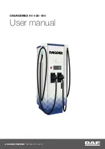
. The 10-gauge black wire from the onboard computer connects to the B– terminal on
the speed controller, and the 6-gauge black wire (also on the controller B– terminal) goes through the onboard
computer and connects to the negative (–) post of battery no. 4. The positive terminal of the charger recepta-
cle is connected to the positive (+) post of battery no. 1. The gray wire from the onboard computer is con-
nected to the charger receptacle.
If the charger works with one vehicle, but does not work with another vehicle, then most likely the problem is
in the vehicle charge circuit. Check wire continuity and connections between the charger receptacle, onboard
computer and batteries.
Figure 6-4 Charge Circuit and Style A Battery Configuration – 4 x 12-Volt Precedent Vehicles
S1
S2
B+
M–
B–
1
2
3
4
#10 BLA
CK
#6 RED
#6 BLA
CK
#6 BLA
CK
#6 BLACK
BATTERY
BANK
#10 BLA
CK
#10 RED
#18 GRA
Y
ONBOARD
COMPUTER
FRONT
OF VEHICLE
SINGLE
POSITION
CONNECTOR
CHARGER
RECEPTACLE
SPEED
CONTROLLER
TO SOLENOID
Содержание 2008-2011
Страница 2: ......
Страница 12: ...Page x 2008 2011 Domestic Battery Charger Maintenance and Service Manual ...
Страница 18: ...1 ...
Страница 28: ...2 ...
Страница 64: ...3 ...
Страница 100: ...4 ...
Страница 132: ...5 ...
Страница 168: ...6 ...
Страница 204: ...7 ...
Страница 296: ...Club Car R NOTES ...
Страница 298: ......
Страница 299: ......