background image

Z4-8

MK3

 Installation and User Guide v1.2

12

Facility Ports

Each zone of the mixer is provided with a Facility Port in 
the form of a rear panel 8-way RJ45 connector. The primary 
use of the Facility Port is for the connection of LM-2 remote 
active input modules, but it may also be used as a general-
purpose, per-zone auxiliary balanced input (see “Using the 
Facility Ports as auxiliary zone inputs” on page 18 f
or more 

information on this application). Note that audio connected 

via a Facility Port will only appear at the same-numbered 
Zone Output, and no other.
The active modules operate on DC power supplied by the 
mixer. The current consumed by each module is minimal and in 
the vast majority of installations there will be no power supply 
issues. Nevertheless, installers are urged to check the data in 
the Appendix regarding PSU capacity (see “PSU capability and 
optional device current consumption” on page 24

).

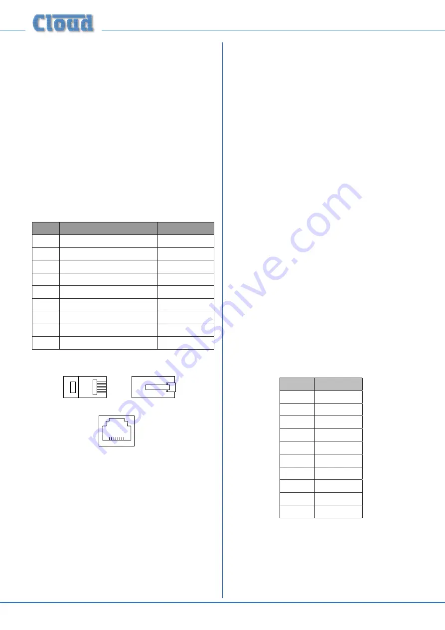
The pinout of the Facility Port connector is given in the table 
below:

PIN

USE

Cat 5 CORE*

1

Audio ‘cold’ phase (-)

White + Orange

2

Audio ‘hot’ phase (+)

Orange

3

Priority VCA  control

White + Green

4

+  15 V

Blue

5

0 V

White + Blue

6

-15 V

Green

7

Music level control (0 to 10 V)

White + Brown

8

Music source select control (0 to 10 V)

Brown

SCN

Screen for system music controls

Connector shell

* Standard wiring for pre-made cables







Please also refer to “LM-2 active input modules – general 
considerations” on page 18
 for further information 
regarding installation of remote active input modules.

Connecting an LM-2 remote input module

The LM-2 should be connected to a Facility Port using 
screened Cat 5 cable. (Note that as the cable carries analogue 
audio, 

only

 screened Cat 5 should be used.)


All 8 cores are 

used.


The LM-2 includes controls for local music level and 

source selection, the wiring for these functions being catered 
for on the Facility Port. Thus it is not necessary to make any 
connections to the Zone’s Music Control Port

.

The  LM-2’s  upper  PCB  is  fitted  with  an  RJ45  connector 

labelled OUTPUT. Connect this to the Facility Port of the 
relevant Zone using screened Cat 5 cable with screened 
RJ45s at each end. Follow the colour coding shown in the 
previous table. The metal screening of the connectors should 
be bonded to the screen of the cable. Full details can be found 
in the LM-2 Installation Guide.
The second RJ45 connector on the LM-2, ‘LINK’, may be used 

to “daisy-chain” additional LM-2s, thus allowing multiple input 
modules to be installed at different locations in the zone.  See 
the LM-2 Installation Guide for more details.
Before the LM-2’s music source and level controls will operate, 
set the MUSIC CONTROL push-button switch ([14] on page 
9

)  for  the  Zone  where  the  LM-2  is  installed  to  REMOTE 

(i.e., pressing it in). In this setting, the Zone’s front panel Music 

Level and Source Select controls become inoperative.
Sometimes it is desirable to permit remote control of music 
level but keep music source selectable only on the mixer. In 
this case, internal jumper J1 on the sub-board for the Zone in 
use should be moved from ‘SW’ to ‘FR’. This will render the 
LM-2’s music source switch inoperative, and return source 
selection to the front panel. See page 22 for full details and 
jumper locations.

Paging System connections

Cloud PM Series paging microphones may be connected 
directly to the Z4

MK3

 and Z8

MK3

.

Two connections are required: the paging mic audio signal 
should be connected to the Paging Mic Input ([6] on page 
9

)  and  the  control  cable  to  the  10-pin  Zone Access  port 

([9] on page 9

).  The  pinout  of  the  Zone  Access  port  is 

given below:

PIN NO.

FUNCTION

1

0 V

2

Zone 1

3

Zone 2

4

Zone 3

5

Zone 4

6

Zone 5

7

Zone 6

8

Zone 7

9

Zone 8

10

+15 V

Connecting a PM4/4SA/8/8SA/12/16 paging mic

These microphones are equipped with both digital and 
analogue paging interfaces; the Z4

MK3

 and Z8

MK3


use the 

analogue interface. PM microphones are available in 4, 8, 
12 or 16-zone versions; the installer should be sure he/she 
understands how paging zones correspond to mixer zones 
before commencing wiring.

Содержание Z4MK3

Страница 1: ...10 0 Zone 2 10 0 10 0 10 0 10 0 Zone 3 10 0 10 0 10 0 10 0 Zone 4 10 0 10 0 10 0 10 0 MK3 1 2 3 4 5 6 Eight Zone Venue Mixer 8 Power Mute Zone 1 Zone 2 Zone 3 Zone 4 Zone 5 Zone 6 Zone 7 Zone 8 Music...

Страница 2: ...eatures 5 Optional System Components 6 LM 2 Mic line input module with remote music control 6 RSL 6 Series Remote Music Level source Control 6 PM Series paging microphones 7 PM1 paging microphone 7 Bl...

Страница 3: ...17 Microphone priority over input at Facility Port 17 OPTIONS AND ADDITIONAL INFORMATION 18 LM 2 active input modules general considerations 18 Connecting multiple LM 2s 18 Using the Facility Ports as...

Страница 4: ...t magnitude to constitute a risk of electric shock The exclamation point within an equilateral triangle is intended to alert the user to the presence of important operating and maintenance servicing i...

Страница 5: ...technical specifications The Z8MK3 Z4MK3 manual includes full details of the optional LM 2 remote input module Basic information on interfacing Cloud PM Series paging microphones and connecting the RL...

Страница 6: ...Control Plate permitting control of zone music level and source The LM 2 connects to one of the unit s Facility Ports via screened Cat 5 cable and the remote inputs are fed to that zone only The mixer...

Страница 7: ...12 16 paging mic on page 12 for more information PM1 paging microphone The Cloud PM1 paging microphone is also compatible with the Z8MK3 and Z4MK3 It is a much simpler unit which addresses only one zo...

Страница 8: ...HONE 1 adjusts the level of the microphone connected at Mic 1 input in each zone See page 15 4 MICROPHONE 2 adjusts the level of the microphone connected at Mic 2 input in each zone See page 15 5 PAGI...

Страница 9: ...7 PAGING MIC GAIN as 4 See page 16 8 PAGING MIC EQ as 5 See page 16 9 PAGING MIC ACCESS PORT 6 pin Z4MK3 or 10 pin Z8MK3 5 mm pitch screw terminal connector for per zone contact closure paging access...

Страница 10: ...r has an extra cavity for storing a spare fuse note that the active fuse is that in the inner cavity System Connections Music Sources Connect the system s various music sources to LINE 1 to LINE 6 All...

Страница 11: ...pin 2 cold pin 3 hot When using single core cable don t connect cold at the Z8II Z4II Unbalanced input e g phono 1 3 2 SC SCN Z8II Z4II Balanced output pin 1 ground pin 2 cold pin 3 hot Unbalanced in...

Страница 12: ...Zone s Music Control Port The LM 2 s upper PCB is fitted with an RJ45 connector labelled OUTPUT Connect this to the Facility Port of the relevant Zone using screened Cat 5 cable with screened RJ45s a...

Страница 13: ...responding to the zone s in which announcements are required Any or all of the zones may be paralleled if multiple zones need to operate from the PM1 An alternative method for achieving paging to all...

Страница 14: ...fore the RSL 6 will operate the zone s Music Control Port must be enabled by setting the adjacent push button switch 14 on page 9 to REMOTE i e pressing it in In this setting the zone s front panel Mu...

Страница 15: ...e rear panel switch setting the front panel control in LOCAL and via a remote plate or other external control in REMOTE If the jumper is set to FR the source selection will always be made with the fro...

Страница 16: ...via internal jumpers and should be set to suit the requirements of the installation when the system is installed See page 22 for location of the internal jumpers Mic 1 Mic 2 priority By default fully...

Страница 17: ...the priority is selected a signal present at Line 6 will force the zone s source selection to that input when the signal disappears the previously selected source will be restored over the time const...

Страница 18: ...acility Port the chain is connected Remember to consider the current drawn by any additional input modules see page 24 for details of current consumption and PSU capability See also the section below...

Страница 19: ...hey may be used to receive DC voltages from the external system to effect these adjustments Both music source selection and level can be controlled over their full ranges with a DC voltage of 0 to 10V...

Страница 20: ...to be selected The output impedance of the control voltage source should be low enough to overcome the effect of this resistor Fitting loudspeaker EQ cards The Z4MK3 and Z8MK3 are compatible with vari...

Страница 21: ...system where four possible music or other audio sources are made available to three or more zones areas Only three are shown for clarity Points to note Area 1 and Area 3 have remote control plates in...

Страница 22: ...ase time ABSENT 12 seconds release time 3S J4 Mic priority over facility input OFF No priority ON MIC 1 2 paging mic haveVOX triggered priority over signals at facility port OFF J5 Paging mic priority...

Страница 23: ...E 7 Z8MK3 ONLY KEY Jumper with two possible positions black square indicates factory default setting J1 J2 J3 J4 Motherboard jumper locations SOCKET FOR OPTIONAL EQ CARD J8 J1 J4 J5 J2 J6 COMPONENT SI...

Страница 24: ...fending signal source can often be identified by setting the volume control to minimum then disconnecting the input leads both left right channels on each line input until the hum disappears This prob...

Страница 25: ...Impedance 2 kohms balanced Phantom power 15V PCB jumper for on off Headroom 20 dB Noise 120 dB EIN 22 Hz 22 kHz 150 ohms Equalisation HF 10 dB 5 kHz LF 10 dB 100 Hz Facility Input Input Impedance 10...

Страница 26: ...Z4 8MK3 Installation and User Guide v1 2 26...

Страница 27: ...Z4 8MK3 Installation and User Guide v1 2 27...

Страница 28: ...Z4 8MK3 Installation and User Guide v1 2 28...

Страница 29: ...Z4 8MK3 Installation and User Guide v1 2 29...

Страница 30: ...Z4 8MK3 Installation and User Guide v1 2 30...

Страница 31: ...Z4 8MK3 Installation and User Guide v1 2 31...

Страница 32: ...ngland Tel 44 0 114 244 7051 Fax 44 0 114 242 5462 email info cloud co uk web www cloud co uk Cloud Electronics USA 2065 Sidewinder Drive Suite 200 Park City Utah 84060 United States of America Toll F...

Отзывы: