


M01W
45H
6-0
6
WSAT-SC
75C-180F
- S T AR T - U P -
33
VERIFY TENSIONS – ABSORPTIONS
Check that the temperatures of the fluids are included in the WORKING LIMITS.
If the controls of the previous paragraphs are positive, it is possible to restart the unit.
For information on the control panel, refer to the paragraph SETTING.
While the unit is working (ATTENTION ELECTRIC RISK: WORK SAFETLY) check:
•
Power supply tension
•
Phase
unbalance
•
Total absorption of the unit
•
Absorption of the single electric loads
UNIT EQUIPPED WITH SCROLL COMPRESSORS
The GENERAL TECHNICAL DATA table shows the type of compressor on the unit.
The Scroll compressors have only one direction of rotation.
In the event that the direction is reversed, the compressor will not be damaged, but its noisiness will increase and
pumping will be negatively affected. After a few minutes, the compressor will stop because of the activation of the
thermal protection. In this event, cut the power and reverse the 2 phases on the machine power.
Prevent the compressor from working with in reverse rotation: more than 2-3 anomalous starts up can damage it.
Make sure the direction of rotation is correct, measure the condensation and suction pressure. Pressure must clearly
differ: at the start, the suction pressure decreases whilst the condensation pressure increases.
The phase optional monitor, which controls the phase sequence, can be installed later.
REMOTE INPUT CONFIGURATIONS
Check used remote inputs are activated (ON-OFF etc.) as given in the instructions in the ELECTRIC WIRING chapter.
SETTING THE SET-POINT
Check if it is necessary to modify the set-points shown in the SETTING chapter.
EVAPORATOR WATER-FLOW CHECK
Verify that the difference between the water at the input and at the output of the exchanger is related to the capacity
according to the formula:
refrigerating capacity of the unit (kW) x 860 = Dt (°C) x flow rate (L/h).
The refrigerating capacity is shown in the GENERAL TECHNICAL FEATURE chart of this manual and it refers to specific
water/air conditions or to the tables of COOLING PERFORMANCES on TECHNICAL CHART that refer to different use
conditions.
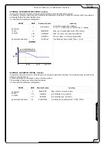
Verify the loss of charge of the exchanger at the water side:
•
determine the water capacity
•
measure the difference of pressure between the input and output of the exchanger and compare it with the
graph LOSS OF CHARGE OF THE EXCHANGER AT THE WATER SIDE
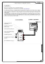
The pressure measurements will be easier if “M” gauges are installed as shown in the HYDRAULIC CONNECTION
DIAGRAM.
REFRIGERANT CIRCUIT PARAMETER CHECK
Detecting the operational conditions is useful to control the unit along time: the performed records must be kept and be
available during maintenance interventions.
When the unit works in stable conditions and according to the operating limits, take note of the following data:
1. compressor discharge temperature (WARNING – BURN DANGERI)
2. condensing
pressure
3. liquid
temperature
4. dehydrator filter upstream and downstream temperature
5. inlet
pressure
6. inlet
temperature
7. exchanger inlet water temperature
8. exchanger outlet water temperature
9. external air temperature (battery input)
10. air temperature coming out from fans
Содержание WSAT-SC 100D Series
Страница 2: ......