background image

40 

WSAN-XSC3 90.4-240.4 

8  Maintenance

8.1  General description

Maintenance must be done by authorized centres or by qualified personnel.
The maintenance allows to:

 maintain the unit efficiency

 increase the life span of the equipment

 assemble information and data to understand the state of the unit efficiency and avoid possible damages

Before checking, please verify the following:

 the electrical power supply line should be isolated at the beginning

 the unit isolator is open, locked and equipped with the suitable warning

 make sure no tension is present

After turning off the power, wait at least 5 minutes before accessing to the electrical panel or any other electrical component.

Before accessing check with a multimeter that there are no residual stresses.

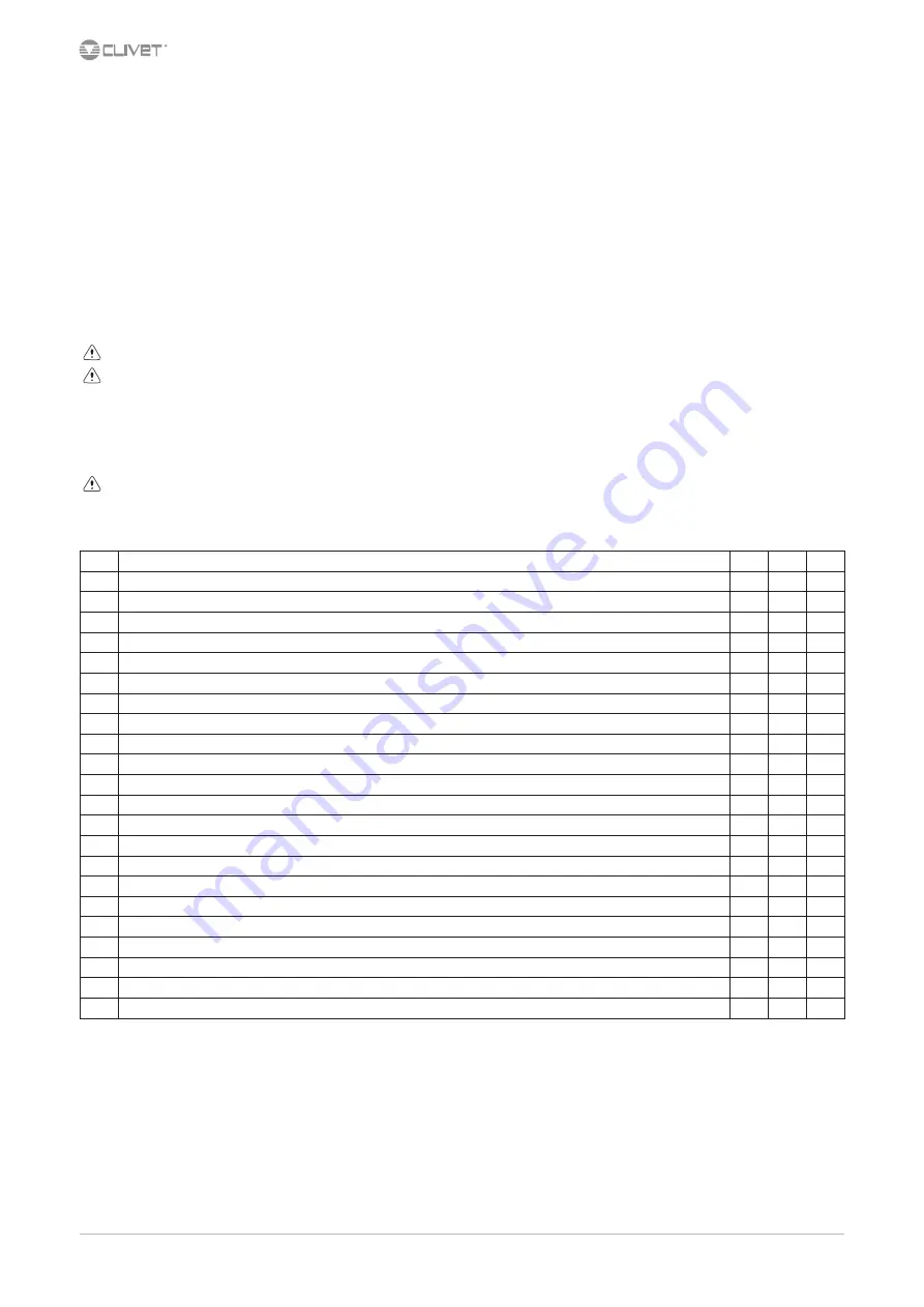
8.2  Inspections frequency

Perform an inspection every 6 months minimum.
The frequency, however, depends on the use.

In the event of frequent use it is recommended to plan inspections at shorter intervals:

 frequent use (continuous or very intermittent use, near the operating limits, etc)

 critical use (service necessary)

intervention frequency (months)

1

6

12

1

presence corrosion

X

2

panel fixing

X

3

fan fixing

X

4

coil cleaning

X

5

water filter cleaning

X

6

water: quality, ph, weight of glycol (%)

X

7

check the exchanger efficiency

X

8

circulating pumps

X

9

check of the fixing and the insulation of the power lead

X

10

check of the earthing cable

X

11

electric panel cleaning

X

12

capacity contactor status

X

13

termina closing, cable insulation integrity

X

14

voltage and phase unbalancing (no load and on-load)

X

15

absorptions of the single electrical loads

X

16

test of the compressor crankcase heaters

X

17

Checking for leaks

*

18

survey of the refrigerant circuit operating parameters

X

19

safety valve

*

20

protective device test: pressure switches, thermostats, flow switches etc..

X

21

control system test: setpoint, climatic compensations, capacity stepping, water / air flow-rate variations

X

22

control device test: alarm signalling, thermometers, probes, pressure gauges etc..

X

* Refer to the local regulations; and ensure correct adherance. Companies and technicians that effect interventions of installation, maintenance/re-

pairs, leak control and recovery must be CERTIFIED as expected by the local regulations. The leak control must be effected with annual renewal.

Содержание WSAN-XSC3 100.4

Страница 1: ...M08N40B16 04 03 10 2019 WSAN XSC3 90 4 240 4 Installation and operating manual High efficiency air cooled reversible heat pump for outdoor installation ...

Страница 2: ...the installation and maintenance cost for the life cycle of the system The purpose of this manual is to provide you with information that is useful from reception of the equipment through installation operational usage and finally disposal so that this advanced system offers the beat solution Yours faithfully CLIVET Spa The data contained in this manual is not binding and may be changed by the man...

Страница 3: ...description 4 2 Reception 6 3 Positioning 8 4 Water connections 10 5 Electrical connections 13 6 Start up 20 7 Control 28 8 Maintenance 40 9 Accessories 46 10 Decommissioning 52 11 Residual risks 53 12 Technical information 54 13 Dimensional drawings 55 ...

Страница 4: ...rsonnel they may cause damages to things and injuries people 1 4 Intended use Use the unit only for cooling heating water or a water and glycol mix keep to the limits foreseen in the technical schedule and in this manual The manufacturer accepts no responsibility if the equipment is used for any purpose other than the intended use 1 5 Installation Outdoor installation The positioning hydraulic sys...

Страница 5: ... the unit Contact a service centre authorized by the manufacturer The installer must train the user particularly on Start up shutdown Set points change Standby mode Maintenance What to do what not to do in case of breakdown 1 12 Unit indentification The serial number label is positioned on the unit and allows to indentify all the unit features The matriculation plate shows the indications foreseen...

Страница 6: ... of receipt to supplier and the carrier Any disputes must be made within 8 days from the date of the delivery Complaints after this period are invalid 2 1 Storage Observe external packaging instructions 2 2 Handling 1 Verify unit weight and handling equipment lifting capacity 2 Identify critical points during handling disconnected routes flights steps doors 3 Suitably protect the unit to prevent d...

Страница 7: ...age the unit Keep packing material out of children s reach it may be dangerous Recycle and dispose of the packaging material in conformity with local regulations A B A Supports for handling remove after the handling B Remove the coil protective mesh before the start up ...

Страница 8: ...he unit raised from the ground verify unit weight and bearing point capacity verify that all bearing points are aligned and leveled condensate water draining consider the maximum possible snow level Avoid installations in places subject to flooding Protect the unit with suitable fence in order to avoid access to unauthorised personnel children vandals etc A correct circulation of the air is mandat...

Страница 9: ...upport For details see 9 Accessories p 46 3 6 Condensate water When a heat pump is running it produces a considerable amount of water due to the defrosting cycles of the external coil The condensate must be disposed in order to avoid damages to people and things ...

Страница 10: ... freezing If the unit or the relative water connections are subject to temperatures close to 0 C mix water with glycol or safeguard the pipes with heating cables placed under the insulation or empty the system in cases of long non use 4 3 Anti freeze solution The use of an anti freeze solution results in an increase in pressure drop Make sure that the glycol type utilized is inhibited not corrosiv...

Страница 11: ...e installation pipe and the evaporator using the joint Do not weld the system pipe with the Victaulic connection joint attached The rubber gasket might be irreparably damaged 4 8 Water filter Use filter with mesh pitch 1 6 mm It must be installed immediately in the water input of the unit in a position that is easily accessible for cleaning The filter never should be removed this operation invalid...

Страница 12: ...ter fill and drain the system several times 2 Apply additives to prevent corrosion fouling formation of mud and algae 3 Fill the plant 4 Execute leakage test 5 Isolate the pipes to avoid heat dispersions and formation of condensate 6 Leave various point of service free wells vent holes etc Neglecting the washing will lead to several filter cleaning interventions and at worst cases can cause damage...

Страница 13: ... full load input full load power input at max admissible condition Electrical wiringdiagram Nr 5 2 Connections 1 Refer to the unit electrical diagram the number of the diagram is shown on the serial number label 2 Verify that the electrical supply has characteristics conforming to the data shown on the serial number label 3 Before starting work ensure the unit is isolated unable to be turned on an...

Страница 14: ... bar Cu section mm 2 x 30 x 5 2 x 30 x 5 2 x 30 x 5 Max bar Cu width mm 50 50 50 Tightening torque Nm 20 20 20 5 6 Connections performer by customer ALM cumulative fault signal QMP pump protection automatic device AP18 demand limit SA1 remote on off AP19 water reset SA1 1 second setpoint enabling switch APUI inverter user side SA6 sanitary hot water cycle switch APV 0 10V analogical output for fre...

Страница 15: ...g center 4 select Modify board setting 5 select Local area connection LAN 6 select Internet protocol version 4 TPC IPV4 and enter Property 7 set the IP address 192 168 1 100 8 set Subnet mask as 255 255 255 0 9 confirm OK 10 enter Start Windows button 11 write the command cmd and enter do it 12 write and run the command Ping 192 168 1 42 13 the message connection is OK will appear when successful ...

Страница 16: ...e up to 350 mt A User interface 2 Distance up to 700 mt B B1 KNX bus max 350 mt twisted pair with shield ø 0 8 mm EIB KNX cable marking recommende C PSX Mains power supply unit pwer supply unit N125 11 5WG1 125 1AB11 C1 AC 120 230V 50 60Hz D KNX bus max 350 mt ...

Страница 17: ...06A Every RS485 serial line must be set up using the In Out bus system Other types of networks are not allowed such as Star or Ring networks The difference in potential between the earth of the two RS485 devices that the cable shielding needs to be connected to must be lower than 7 V There must be suitable arresters to protect the serial lines from the effects of atmospheric discharges A 120 ohm r...

Страница 18: ...ellow startup red flashing software error red flashing communicating not possible fixed hardware error communication down 5 11 BACnet IP Option LED BSP communication with AP1 module LED BUS communication with BACnet green communication ok green ready for communication yellow software ok but communication with AP1 down yellow startup red flashing software error red BACnet server down fixed hardware...

Страница 19: ...WSAN XSC3 90 4 240 4 19 5 12 Remote ON OFF Do not perform short On Off cycles Do not use the remote On Off with thermoregulation function A B A B YES NO B A B ...

Страница 20: ...al spaces 4 air flow correct return and supply no bypass no stratification 5 structure integrity 6 fans run freely 7 unit on vibration isolators 8 unit input water filter shut off valves for cleaning 9 vibration isolators on water connections 10 Minimum system water content 11 expansion tank indicative volume 5 system content 12 cleaned system 13 loaded system possible glycol solution corrosion in...

Страница 21: ...4 Safety temperature C 1 4 10 19 6 6 Electric Circuit Verify that the unit is connected to the ground plant Check the conductors are tightened as the vibrations caused by handling and transport might cause these to come loose Connect the unit by closing the sectioning device but leave it on OFF Check the voltage and line frequency values which must be within the limits 400 3 50 10 Check and adjust...

Страница 22: ...o limit the absorbed electric power with an external signal 0 10 Vcc The higher the signal is the lower the number of compressors available to meet the thermal need If only P0002 EnDemandLimit 0 Path Main Menu Unit parameters Demand limit Step Display Action Menu Variable Keys Notes 1 Press 3 sec 2 Password Set Password 3 Press 4 Main menu Select Unit parameters 5 Unit parameters Select Set Point ...

Страница 23: ...ss 3 sec 10 Select Local connections Path Main Menu Unit parameters TExt Correction config Parameters Short description Description P0606 CSptLow setpoint temperature value when the air temperature value is AirAtSptLowC P0607 AirAtSetPointLowC external air temperature value where the calculated setpoint takes on the value given by CSptLow P0608 CSptHigh setpoint temperature value when the air temp...

Страница 24: ...reset 6 Water reset Select Parameter 7 Set 8 Confirm 9 Press 3 sec 10 Select Local connections Path Main Menu Unit parameters Water reset Parameters Short description Description P0616 MaxCWRC Maximum correction to be applied to the setpoint Cooling P0617 SWRMaxC Value of the WR control signal corresponding to the correction of the set Cool equal to P0616 P0618 SWRMinC Value of the WR control sign...

Страница 25: ...0 8 mm use an EIB KNX cable Possible connections Tree star in out bus mixed It is not possible to use a ring connection No end of line resistor or terminator required There must be suitable arresters to protect the serial lines from the effects of atmospheric discharges The data line must be kept separate from the power conductors or powered at different voltage values and away from possible sourc...

Страница 26: ...nt3 plus optimal H2O temperature control MODE C The master manages the single cooling The master optimizes individual refrigerant circuits Active pumps only with active compressors P0658 2 P0657 0 C setpoint1 setpoint2 setpoint3 plus minimum pumps consumption need balanced system t1 t2 t3 Path Main Menu Unit parameters Master Slave Parameters Short description Description P0655 LNinstalledUnits Nu...

Страница 27: ... a compressor for at least ten minutes If the average times are close to this limit take the proper corrective actions 6 18 Start up report Identifying the operating objective conditions is useful to control the unit over time With unit at steady state i e in stable and close to work conditions identify the following data total voltages and absorptions with unit at full load absorptions of the dif...

Страница 28: ...et temperature utility side D T OutH2OUtilitySide Water outlet temperature utility side E ActualState On off eco pmp On F ActualMode Cool water cooling Heat HEATING 2 Installed compressors 1 0 Compressors ON example circuit 1 1 compr On circuit 2 0 compr On 50 Heating capacity 7 3 Keys Symbol Name Description Info Main menu Alarm Alarm display Cancel Exit Previous level Keyboard settings Up Increa...

Страница 29: ...at HEATING 4 Confirm 5 Exit 7 6 Modify setpoint Step Display Action Menu Variable Keys Notes 1 Press 2 Main menu Select Unit parameters 3 Unit parameters Confirm Set Point 4 Select Set Point 5 Set Set Point 6 Confirm 7 Exit Parameters Short description Description P0583 SetPointCooling Setpoint Cool P0584 2SetPointCooling 2 Setpoint Cool Enable by remote switch P0855 SetPointECOCooling Economic su...

Страница 30: ...Confirm 7 Select Value 8 Set On Eco 9 Confirm 10 Exit Enable Scheduler Step Display Action Menu Variable Keys Notes 1 Press 3 sec 2 Password Set Password 3 Press 4 Main menu Select Unit Parameters 5 Select Option config 6 Set P0052 1 7 Press 3 sec Select Local connections Unit Parameters menu is displayed 7 8 Display the status Step Display Action Menu Variable Keys Notes 1 Press 2 Main menu Selec...

Страница 31: ...Pump 3 Command 83 User side Inverter Command 84 User side Inverter Signal 85 User side Inverter Reset 86 Pump On for Anti freeze 87 Anti freeze Heaters User side 88 User side Flow Request 89 LimitFlow Heating 90 LimitFlow Recovery 91 LimitFlow Cooling 92 User side Pump 1 Hours 93 User side Pump 2 Hours 94 User side Pump 3 Hours Nr CIRCUIT 1 STATA 1001 Current Schema 1 1 1002 SubCooling 1003 Curren...

Страница 32: ...rotection 1182 Compressor 2 1 Protection 1184 Source Fan 1 1 Protection 2180 High Pressure 1 2 2181 Compressor 1 2 Protection 2183 Compressor 2 2 Protection 2184 Source Fan 1 2 Protection Nr ANALOGIC INPUT 201 Demand Limit 202 User side Differential Pressure switch 203 Free cooling Water Temperature 204 External Air Temperature 205 Recovery In Temperature 206 Recovery Out Temperature 207 Cabinet T...

Страница 33: ...1 Aries Defrost Injection 1 1 1302 Source Pump 1 1 Command 1303 Compressor 1 1 Command 1304 Compressor 2 1 Command 1305 Liquid Injection 1 1 1306 Liquid Injection 2 1 1307 RecValve Battery 1 1 1308 RecValve Chiller 1 1 1309 RecValve Recovery 1 1 1310 Reversing Cycle Valve 1 1 2301 Aries Defrost Injection 1 2 2302 Source Pump 2 1 Command 2303 Compressor 1 2 Command 2304 Compressor 2 2 Command 2305 ...

Страница 34: ...sible damage Example eE0001 Phase monitor Fault active alarm EE0003 Pum 1 faulty Ok resetted alarm Display of alarm step 1 3 Reset allarm step 4 10 Step Display Action Menu Variable Keys Notes 1 Press 2 Alarm list detail Press 3 Alarm list Select Alarm 4 Alarm list detail Press 3 sec 5 Password Set Enter password 6 Alarm list detail Press 7 Alarm list Select Alarm 8 Select Reset Executed 9 Press 3...

Страница 35: ...erature probe fault HW ee0030 DemandLimit Demand limit fault HW ee0031 WaterReset Water reset fault HW ee0032 External Humidity probe Error Relative humidity probe fault HW ee0033 T Quadro Ele Electrical panel temperature probe fault HW ee0035 YV Cool Open YV Cool opening fault 4P ee0036 YV Heat Open YV Heat opening fault 4P ee0037 YV Cool Close YV Cool closing fault 4P ee0038 YV Heat Close YV Hea...

Страница 36: ...arge temperature probe fault HW Circuit 1 ee1025 T Source 1 Source 1 temperature probe fault HW Circuit 1 ee1026 T Source 2 Source 2 temperature probe fault HW Circuit 1 ee1027 T Suction Gas Suction temperature probe fault HW Circuit 1 ee1028 P Discharge High pressure probe fault HW Circuit 1 ee1029 P Suction Low pressure probe fault HW Circuit 1 ee1030 T GasRecovery Recovery exchanger gas tempera...

Страница 37: ...rce Pump 1 protection Source side pump 1 overload protection Source 2 EE2014 Source Pump 2 protection Source side pump 2 overload protection Source 2 EE2015 Source Pump 3 protection Source side pump 3 overload protection Source 2 EE2018 Source side protection Source side ventilation overload protection Circuit 2 ee2022 T Discharge C1 1 Compressor 1 discharge temperature probe fault HW Circuit 2 ee...

Страница 38: ... User side ECV connection problem HW Circuit 2 ee2071 Source ECV 1 1 Source side ECV 1 connection problem HW Circuit 2 ee2072 Source ECV 2 1 Source side ECV 2 connection problem HW Circuit 2 REFRIGERANT CIRCUIT ALARMS Num Name Description Category ff1005 Min overheating EEV1 Value of refrigerant superheat too low EEV1 user side Circuit 1 ff1006 Min overheating EEV2 Value of refrigerant superheat t...

Страница 39: ...mperature for defrost Circuit 2 ff2049 DFRTimeMax Defrost Time Circuit 2 HYDRAULIC CIRCUIT ALARMS Num Name Description Category iI0002 Water pressure User side low water pressure GP Ut iI0006 Flow switch utility side User side low flow rate GP Ut II0007 Freeze alarm User side Water Frost Protection Centrale ii0008 Pumps antifreeze alarm Pump activation Water Frost Protection Centrale II0009 Incons...

Страница 40: ...e service necessary intervention frequency months 1 6 12 1 presence corrosion X 2 panel fixing X 3 fan fixing X 4 coil cleaning X 5 water filter cleaning X 6 water quality ph weight of glycol X 7 check the exchanger efficiency X 8 circulating pumps X 9 check of the fixing and the insulation of the power lead X 10 check of the earthing cable X 11 electric panel cleaning X 12 capacity contactor stat...

Страница 41: ... the surface Using an air pressure gun clean the aluminum surface of the battery be careful to direct the air in the opposite direction of the fan air movement Hold the gun parallel to the fins to avoid damages As an alternative vacumn cleaner can be used to suck impurities from the air input side Verify that the aluminum fins are not bent or damaged in the event of damages contact the authorized ...

Страница 42: ... of the insulations if necessary apply glue and and renew the seals 8 10 Water filter Check that no impurities prevent the correct passage of water 8 11 Flow Switch controls the operations remove incrustations from the palette 8 12 Compressor supply line shut off valve A A Supply line shut off valve Do not remove the seal Remove only if authorized by the manufacturer Please contact the maker for i...

Страница 43: ...oled solution 5 protect the exchanger from the air 6 remove the drain plugs to the pumps Any anti freeze liquid contained in the system should not be discharged freely as it is a pollutant It must be collected and reused Before starting a washing the plant Example emptying pump B It s recommended that the re start after the stopping period is performed by a qualified technician especially after se...

Страница 44: ...44 WSAN XSC3 90 4 240 4 8 17 Compressor replacement ...

Страница 45: ...WSAN XSC3 90 4 240 4 45 8 18 Exchanger replacement ...

Страница 46: ...24P RX603 104Pr RZ605 X102Pr RZ620 124P RX403 Z208 112Pr RZ605 X102Pr PE8T00057 RZ424 X207 108P RX603 104Pr RX503 Z205Pr RZ424 X207 108P RX403 Z208 112Pr RX503 Z205Pr PE8T00058 RZ620 124P RX604 107P RZ620 124P RX604 107P PE8T00059 RZ620 124P RX604 107P RX503 Z205Pr RZ620 124P RX704P RX503 Z205Pr PE8T00060 RZ424 X207 108P RZ420 212 X107P RX504 Z212P RZ424 X207 108P RX704P RX504 Z212P PE8T00061 RZ62...

Страница 47: ...WSAN XSC3 90 4 240 4 47 ...

Страница 48: ...48 WSAN XSC3 90 4 240 4 ...

Страница 49: ...WSAN XSC3 90 4 240 4 49 ...

Страница 50: ...n valve 2 Cutoff valve 12 pressure switch of the charged system 3 Purge valve 13 Anti ice electric heater 4 Storage tank CSVX Couple of manually operated shut off valves 5 drain valve IFWX Steel mesh strainer on the water side 6 Cutoff valve PD Differential pressure switch 7 Steel mesh strainer T Temperature probe 8 Pressure gauge TWin Water inlet 9 Safety valve 6 Bar TW out Water outlet 10 Electr...

Страница 51: ...e 12 pressure switch of the charged system 3 Purge valve 13 Anti ice electric heater 4 Storage tank CSVX Couple of manually operated shut off valves 5 drain valve IFWX Steel mesh strainer on the water side 6 Cutoff valve PD Differential pressure switch 7 Steel mesh strainer T Temperature probe 8 Pressure gauge TWin Water inlet 9 Safety valve 6 Bar TW out Water outlet 10 Electric pump ...

Страница 52: ... equipment must be disposed of together with all of its parts To dispose of household electrical and electronic equipment the manufacturer recommends you contact an authorised dealer or an authorised ecological area Professional electrical and electronic equipment must be disposed of by authorised personnel through established waste disposal authorities around the country In this regard here is th...

Страница 53: ...iodically check that all of the panels are correctly closed and fixed If there is a fire the temperature of the refrigerant could reach values that in crease the pressure to beyond the safety valve with the consequent possible projection of the refrigerant itself or explosion of the circuit parts that remain isolated by the closure of the tap Do not remain in the vicinity of the safety valve and n...

Страница 54: ...rnal exchanger water temperature 40 45 C Entering external exchanger air temperature 7 C D B 6 CW B Acoustic configuration super silenced EN General technical data Performance Size 90 4 100 4 110 4 120 4 140 4 160 4 180 4 200 4 220 4 240 4 Cooling Cooling capacity 1 kW 232 255 279 307 355 400 451 499 537 563 Compressor power input 1 kW 82 4 89 3 98 6 115 129 143 166 179 199 224 Total power input 2...

Страница 55: ...8 85 71 62 92 72 110 4 93 90 90 88 88 85 71 62 92 72 120 4 93 90 90 88 88 85 71 62 92 72 140 4 94 91 91 89 89 86 72 63 92 72 160 4 95 92 92 90 90 87 73 64 93 73 180 4 101 97 96 93 89 84 78 72 95 74 200 4 101 97 96 93 89 84 78 72 95 74 220 4 102 98 97 94 90 85 79 73 95 74 240 4 102 98 97 94 90 85 79 73 95 75 The sound levels refer to standard unit with Axitop no accessories at full load in test nom...

Страница 56: ...7 90 69 200 4 96 92 91 88 84 79 73 67 90 69 220 4 97 93 92 89 85 80 74 68 90 69 240 4 97 93 92 89 85 80 74 68 90 70 The sound levels refer to standard unit with Axitop no accessories at full load in test nominal conditions The sound pressure level refers to 1 m from the standard unit outer surface operating in open field Measures are according to UNI EN ISO 9614 2 regulations with respect to the E...

Страница 57: ...ended operating range with air flow rate automatic increasing Inside this field the sound levels are the same of the compressor soundproofing SC acoustic configuration 3 Unit operating range with automatic staging of the compressor capacity 4 Standard unit operating range with air flow automatic modulation 5 Unit operating range in B Low water temperature configuration 40 ethylene glycol 6 Extende...

Страница 58: ... and control device calibrations open closed value High pressure safety pressure switch kPa 4050 3300 Antifreeze protection C 4 5 5 High pressure safety valve kPa 4500 Low pressure safety valve kPa 2950 Max no of compressor starts per hour n 10 High compressor discharge temperature safety thermostat C 140 Exchanger operating range Internal exchanger DPr DPw PED CE 4500 4500 1000 DPr Maximum operat...

Страница 59: ...6 577 604 562 566 577 604 Shipping weight kg 2815 2855 2913 3042 2815 2855 2913 3042 Operating weight kg 2928 2968 3028 3162 2928 2968 3028 3162 Size SC EXC EN EXC 90 4 100 4 110 4 120 4 90 4 100 4 110 4 120 4 Container shipping length mm 4300 4300 4300 4300 4300 4300 4300 4300 Container shipping depth mm 2315 2315 2315 2315 2315 2315 2315 2315 The presence of optional accessories may result in a ...

Страница 60: ...ting weight kg 3588 3602 3588 3602 Size SC EXC EN EXC 140 4 160 4 140 4 160 4 Container shipping length mm 5275 5275 5275 5275 Container shipping depth mm 2315 2315 2315 2315 The presence of optional accessories may result in a substantial variation of the weights shown in the table Fan diffusers are separately supplied 1 External exchanger 2 Antivibration fixing holes Ø 25mm 3 Lifting brackets re...

Страница 61: ...ting weight kg 4347 4399 4347 4399 Size SC EXC EN EXC 180 4 200 4 180 4 200 4 Container shipping length mm 6157 6157 6157 6157 Container shipping depth mm 2315 2315 2315 2315 The presence of optional accessories may result in a substantial variation of the weights shown in the table Fan diffusers are separately supplied 1 External exchanger 2 Antivibration fixing holes Ø 25mm 3 Lifting brackets re...

Страница 62: ... weight kg 4561 4701 4561 4701 Operating weight kg 4816 4956 4816 4956 Size SC EXC EN EXC 220 4 240 4 220 4 240 4 Container shipping length mm 6507 6507 6507 6507 Container shipping depth mm 2315 2315 2315 2315 The presence of optional accessories may result in a substantial variation of the weights shown in the table Fan diffusers are separately supplied 1 External exchanger 2 Antivibration fixin...

Страница 63: ...Page intentionally left blank ...

Страница 64: ...teras Nº 38 Oficina C303 28050 Madrid España Tel 34 91 6658280 Fax 34 91 6657806 info clivet es CLIVET GmbH Hummelsbütteler Steindamm 84 22851 Norderstedt Germany Tel 49 0 40 32 59 57 0 Fax 49 0 40 32 59 57 194 info de clivet com CLIVET RUSSIA Elektrozavodskaya st 24 office 509 107023 Moscow Russia Tel 74956462009 Fax 74956462009 info ru clivet com CLIVET MIDEAST FZCO Dubai Silicon Oasis DSO High ...

Отзывы: