


INSTALLATION AND USER MANUAL
HTM-24E
16
V0REV5ES1218
Temperature probe
The installer has to install the temperature probe B1 in one of the following points:
-
Inside the buffer tank
-
Return water pipe
-
If the buffer tank has a coil, in the return water pipe of the coil
9.
ELECTRICAL CONNECTION
The electric switchboard is located in the front of the module. The installer has to make
the following connections:
1.
Power supply:
Connect the system directly from the general control panel. The minimum wire section
and the characteristics of the circuit breaker that the installer has to install are shown in the
following table:
These data are calculated based on a maximum distance of 15m. In case of higher
distances contact with technical department for a new dimensioning.
2.
Circulator pump
Connect the circulator pump to the heating module. The system will control
automatically the operation of the pump when it is needed.
The connection is single-phase 230V/ 50 Hz. Pump must not exceed 5 A current.
In the Annex 2 and 3, are shown electric schemes. Connect the pump in the terminals 0-0.
Models
Power Supply mm2 Circuit breaker
HTM-24E
380 V/ 3ph
/50 Hz
6
20 A- curve D
Содержание HTM EVI SERIES
Страница 1: ...1 V0REV5ES1218 INSTALLATION AND USER MANUAL HTM EVI SERIES ...
Страница 2: ...INSTALLATION AND USER MANUAL HTM 24E 2 V0REV5ES1218 ...
Страница 21: ...INSTALLATION AND USER MANUAL HTM 24E 21 V0REV5ES1218 12 ANNEX HYDRAULIC SCHEME ...
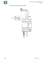
Страница 22: ...22 V0REV5ES1218 ELECTRICAL DIAGRAM THREE PHASE UNITS ...
Страница 24: ...INSTALLATION AND USER MANUAL HTM 24E 24 V0REV5ES1218 ELECTRONIC EXPANSION VALVE DIAGRAM ...


