ClimateMaster Tranquility TTD026 Series Скачать руководство пользователя страница 7

7

c l i m a t e m a s t e r. c o m

T H E   S M A R T   S O L U T I O N   F O R   E N E R G Y   E F F I C I E N C Y

Tr a n q u i l i t y

®

  3 0   ( T T )   S e r i e s

R e v. :   0 7 / 1 8 / 1 3

Horizontal Installation

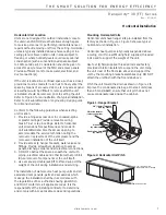
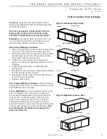
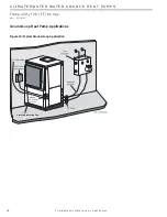
Mounting Horizontal Units

Horizontal units have hanger kits pre-installed from the 

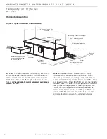
factory as shown in Figure 1. Figure 3 shows a typical 

horizontal unit installation.

Horizontal heat pumps are typically suspended above 

a ceiling or within a soffi t using fi eld supplied, threaded 

rods sized to support the weight of the unit.

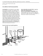
Use four (4) fi eld supplied threaded rods and factory 

provided vibration isolators to suspend the unit. Hang 

the unit clear of the fl oor slab above and support the 

unit by the mounting bracket assemblies only. DO NOT 

attach the unit fl ush with the fl oor slab above.

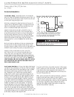
Pitch the unit toward the drain as shown in Figure 2 to 

improve the condensate drainage. On small units (less 

than 2.5 tons/8.8kW) ensure that unit pitch does not 

cause condensate leaks inside the cabinet.

Figure 1: Hanger Bracket

Figure 2: Horizontal Unit Pitch

>PP@7KUHDGHG

5RGE\RWKHUV

9LEUDWLRQ,VRODWRU

IDFWRU\VXSSOLHG

:DVKHU

E\RWKHUV

'RXEOH+H[1XWV

E\RWKHUV

1/4” (6.4mm) pitch
toward drain for drainage

Drain Connection

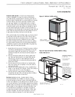
Horizontal Unit Location

Units are not designed for outdoor installation. Locate 

the unit in an INDOOR area that allows enough space 

for service personnel to perform typical maintenance or 

repairs without removing unit from the ceiling. Horizontal 

units are typically installed above a false ceiling or in a 

ceiling plenum. Never install units in areas subject to 

freezing or where humidity levels could cause cabinet 

condensation (such as unconditioned spaces subject 

to 100% outside air). Consideration should be given to 

access for easy removal of the fi lter and access panels. 

Provide suffi cient room to make water, electrical, and 

duct connection(s). 

If the unit is located in a confi ned space, such as a closet, 

provisions must be made for return air to freely enter the 

space by means of a louvered door, etc. Any access panel 

screws that would be diffi cult to remove after the unit 

is installed should be removed prior to setting the unit. 

Refer to Figure 3 for an illustration of a typical installation. 

Refer to unit submittal data or engineering design guide 

for dimensional data.

Conform to the following guidelines when selecting 

unit location:

1.  Provide a hinged access door in concealed-spline 

or plaster ceilings. Provide removable ceiling 

tiles in T-bar or lay-in ceilings. Refer to horizontal 

unit dimensions for specifi c series and model in 

unit submittal data. Size the access opening to 

accommodate the service technician during the 

removal or replacement of the compressor and the 

removal or installation of the unit itself.

2.  Provide access to hanger brackets, water valves and 

fi ttings. Provide screwdriver clearance to access 

panels, discharge collars and all electrical connections.

3.  DO NOT obstruct the space beneath the unit with 

piping, electrical cables and other items that prohibit 

future removal of components or the unit itself.

4.  Use a manual portable jack/lift to lift and support the 

weight of the unit during installation and servicing.

The installation of water source heat pump units and all 

associated components, parts and accessories which 

make up the installation shall be in accordance with 

the regulations of ALL authorities having jurisdiction 

and MUST conform to all applicable codes. It is the 

responsibility of the installing contractor to determine 

and comply with ALL applicable codes and regulations.

Содержание Tranquility TTD026 Series

Страница 1: ...er Performance Data 27 ECM Blower Control 28 Typical Wiring Diagram Units with CXM Board and ECM Fan Motor Single Phase 30 Typical Wiring Diagram Units with ClimaDry Single Phase 31 Typical Wiring Diagram Units with CXM Board 32 ECM Fan Motor and MPC DDC CONTROLS SINGLE PHASE 32 CXM Controls 33 DXM Controls 34 Safety Features CXM and DXM Controls 36 ClimaDry Modulating Reheat Option 38 Unit Starti...

Страница 2: ...2 ClimateMaster Water Source Heat Pumps CL I MATEM ASTER WATER SOURCE HEAT PUMPS Tran q u i l i t y 30 TT Series Rev 07 18 13 This Page Intentionally Left Blank ...

Страница 3: ... S DXM w MPC w Disconnect C CXM N CXM w MPC A CXM E CXM w LON R CXM w MPC G 208 230 60 1 H 208 230 60 3 E 265 60 1 F 460 60 3 Cabinet Insulation OPTION 1 A J K 2 C L M 3 E N P 1 FILTER RAIL RANGE ULTRA QUIET 2 FILTER RAIL 1 FILTER FRAME 2 FILTER FRAME 4 G R S NO YES NO YES YES YES YES YES NO NO NO NO NO NO YES YES YES YES NO NO NO NO NO NO YES YES YES YES NO NO NO NO NO NO YES YES YES YES NO NO NO...

Страница 4: ...n and Service Manual should be read and understood before attempting to service refrigerant circuits with HFC 410A Inspection Upon receipt of the equipment carefully check the shipment against the bill of lading Make sure all units have been received Inspect the packaging of each unit and inspect each unit for damage Ensure that the carrier makes proper notation of any shortages or damage on all c...

Страница 5: ...ing heat pumps General Information Pre Installation Installation Operation and Maintenance instructions are provided with each unit Horizontal equipment is designed for installation above false ceiling or in a ceiling plenum Other unit configurations are typically installed in a mechanical room The installation site chosen should include adequate service clearance around the unit Before unit start...

Страница 6: ...x 30 406 x 762 1 16 x 30 813 x 762 1 20 x 30 508 x 762 1 16 x 30 813 x 762 1 20 x 30 508 x 762 Weight Operating lbs kg 266 121 327 148 416 189 443 201 443 201 Weight Packaged lbs kg 276 125 337 153 426 193 453 205 453 205 Horizontal Air Coil Dimensions h x w in mm 18 x 31 457 x 787 20 x 35 508 x 889 20 x 40 508 x 1016 20 x 45 508 x 1143 20 x 45 508 x 1143 Standard Filter 1 25 4mm Throwaway qty in ...

Страница 7: ...on should be given to access for easy removal of the filter and access panels Provide sufficient room to make water electrical and duct connection s If the unit is located in a confined space such as a closet provisions must be made for return air to freely enter the space by means of a louvered door etc Any access panel screws that would be difficult to remove after the unit is installed should b...

Страница 8: ...hanical room with free return e g louvered door Therefore filter rails are the industry standard and are included on ClimateMaster commercial heat pumps for the purposes of holding the filter only For ducted return applications the filter rail must be removed and replaced with a duct flange or filter rack Canvas or flexible connectors should also be used to minimize vibration between the unit and ...

Страница 9: ...Lift out the access panel and set aside Lift and rotate the discharge panel to the other position as shown being careful with the blower wiring 3 Check blower wire routing and connections for tension or contact with sheet metal edges Re route if necessary 4 Check refrigerant tubing for contact with other components 5 Reinstall top panel and screws noting that the location for some screws will have...

Страница 10: ...n other units connected to the same condensate main since this may cause poor drainage for all units on the line WHEN A VENT IS INSTALLED IN THE DRAIN LINE IT MUST BE LOCATED AFTER THE TRAP IN THE DIRECTION OF THE CONDENSATE FLOW CAUTION Duct System Installation Proper duct sizing and design is critical to the performance of the unit The duct system should be designed to allow adequate and even ai...

Страница 11: ...or etc Any access panel screws that would be difficult to remove after the unit is installed should be removed prior to setting the unit Refer to Figures 7 and 8 for typical installation illustrations Refer to unit submittal data or engineering design guide for dimensional data 1 Install the unit on a piece of rubber neoprene orother mounting pad material for sound isolation The pad should be at l...

Страница 12: ...alled and pitched away from the unit to allow for proper drainage This connection must meet all local plumbing building codes Vertical units utilize a condensate hose inside the cabinet as a trapping loop therefore an external trap is not necessary Figure 10a shows typical condensate connections Figure 10b illustrates the internal trap for a typical vertical heat pump Each unit must be installed w...

Страница 13: ...ose to collapse which reduces water flow rate Install an angle adapter to avoid sharp bends in the hose when the radius falls below the required minimum Insulation is not required on loop water piping except where the piping runs through unheated areas outside the building or when the loop water temperature is below the minimum expected dew point of the pipe ambient conditions Insulation is requir...

Страница 14: ...alve and or J type swivel connection Balancing valves and an external low pressure drop solenoid valve for use in variable speed pumping systems may also be included in the hose kit The piping system should be flushed to remove dirt piping chips and other foreign material prior to operation see Piping System Cleaning and Flushing Procedures in this manual The flow rate is usually set between 2 25 ...

Страница 15: ...er your local sales office should be consulted to determine the antifreeze best suited to your area Freeze protection should be maintained to 15 F 9 C below the lowest expected entering loop temperature For example if 30 F 1 C is the minimum expected entering loop temperature the leaving loop temperature would be 22 to 25 F 6 to 4 C and freeze protection should be at 15 F 10 C Calculation is as fo...

Страница 16: ...Pumps CL I MATEM ASTER WATER SOURCE HEAT PUMPS Tran q u i l i t y 30 TT Series Rev 07 18 13 Ground Loop Heat Pump Applications Figure 13 Typical Ground Loop Application High and Low Voltage Knockouts Vibration Isolation Pad To Thermostat ...

Страница 17: ...ement of the water control valve in Figure 14 Always maintain water pressure in the heat exchanger by placing the water control valve s on the discharge line to prevent mineral precipitation during the off cycle Pilot operated slow closing valves are recommended to reduce water hammer If water hammer persists a mini expansion tank can be mounted on the piping to help absorb the excess hammer shock...

Страница 18: ... desired flow of 1 5 to 2 gpm per ton 2 0 to 2 6 l m per kW is achieved A second method of flow control requires a flow control device mounted on the outlet of the water control valve The device is typically a brass fitting with an orifice of rubber or plastic material that is designed to allow a specified flow rate On occasion flow control devices may produce velocity noise that can be reduced by...

Страница 19: ...ll 0 5 ppm Maximum Maximum Allowable at maximum water temperature Chloride Levels 10 C 24 C 38 C Copper Cupronickel 20ppm NR NR 150 ppm NR NR 304 SS 400 ppm 250 ppm 150 ppm 316 SS 1000 ppm 550 ppm 375 ppm Titanium 1000 ppm 550 ppm 375 ppm Erosion and Clogging Particulate Size and Erosion All 10 ppm of particles and a maximum velocity of 1 8 m s Filtered for maximum 841 micron 0 84 mm 20 mesh size ...

Страница 20: ...ion and sound transmission to the building General Line Voltage Wiring Be sure the available power is the same voltage and phase shown on the unit serial plate Line and low voltage wiring must be done in accordance with local codes or the National Electric Code whichever is applicable WARNING To avoid possible injury or death due to electrical shock open the power supply disconnect switch and secu...

Страница 21: ...its with ECM motors require a four wire power supply with neutral ECM motor is rated 265 vac and is wired between one hot leg and neutral Table 4b Tranquility 30 TT Series Electrical Data Units with Secondary Pump or ClimaDry Reheat Electrical Line Voltage Table 4a Tranquility 30 TT Series Electrical Data Standard Units All TT Units Standard TT Units Model Voltage Code Voltage Min Max Voltage Comp...

Страница 22: ...e Wiring Be sure the available power is the same voltage and phase shown on the unit serial plate Line and low voltage wiring must be done in accordance with local codes or the National Electric Code whichever is applicable Figure 15 Single Phase Line Voltage Field Wiring Three phase wiring is similar except that all three power wires are directly connected to the contactor Unit Power Supply see e...

Страница 23: ...ing temperature associated with thermistor FP1 Note that the FP1 thermistor is located on the refrigerant line between the coaxial heat exchanger and expansion device TXV Therefore FP1 is sensing refrigerant temperature not water temperature which is a better indication of how water flow rate temperature is affecting the refrigeration circuit The factory setting for FP1 is for systems using water ...

Страница 24: ...in open during a unit lockout 2 The valve will draw approximately 25 35 VA through the Y signal of the thermostat Note This valve can overheat the anticipator of an electromechanical thermostat Therefore only relay or triac based thermostats should be used Two stage Units Tranquility 30 TT two stage units should be designed with two parallel valves for ground water applications to limit water use ...

Страница 25: ...oltage Wiring Figure 19 AVM Valve Wiring Figure 20 Taco SBV Valve Wiring From Water Source IN OUT NOTE Shut off valves strainers and other required components not shown Solenoid Valve Flow Regulator To Discharge Stage 1 Stage 2 Figure 21 Two Stage Piping C C Thermostat Y1 1 2 3 Y1 AVM Taco Valve Heater Switch Water Valve Wiring ...

Страница 26: ...ided it has the correct number of heating and cooling stages Figure 22a Auto dehumidification Control Figure 22c Units with ClimaDry Reheat Electrical Thermostat Wiring Figure 22b No Dehumidification Control ATP32U03 or ATA22U01 Thermostat Connection to ECM Control Compressor Compressor Heating Stage 2 Reversing Valve Fan 24Vac Hot 24Vac Common Fault LED Y1 Y2 O G R C L Y Y2 O G R C AL1 ECM Interf...

Страница 27: ...0 1230 790 1430 1750 790 0 75 1 1 1080 1320 660 1200 1470 660 072 0 75 1 4 1620 2190 1050 1270 1650 1050 1690 2230 1050 0 75 1 3 1500 1950 980 1170 1520 980 1600 2100 980 0 75 1 2 1400 1830 910 1100 1420 910 1400 1850 910 0 75 1 1 1320 1700 850 1240 1620 850 Factory shipped on Tap Setting 2 During Auxiliary operation residential units only the CFM will run at the higher if the heating delay jumper...

Страница 28: ...stat for electric heat to operate Consult the submittal data or specifications catalog for the specific unit series and model to correlate speed tap setting to airflow in CFM CFM Adjust Settings The CFM adjust setting allows four selections The NORM setting is the factory default position The or settings adjust the airflow by 5 The settings are used to fine tune airflow adjustments The TEST settin...

Страница 29: ... ECM Motor Low Voltage Connector 1 4 Spade Connections to CXM or DXM Board Thermostat Connections Dehumidification LED Fan Speed Selection DIP Switch Figure 23 ECM Version II Interface Layout The ramp down feature may be eliminated during an ESD Emergency Shut Down situation when using a DXM unit controller A DPDT relay is required to break the line voltage to the ECM motor during ESD This relay c...

Страница 30: ...30 ClimateMaster Water Source Heat Pumps CL I MATEM ASTER WATER SOURCE HEAT PUMPS Tran q u i l i t y 30 TT Series Rev 07 18 13 Typical Wiring Diagram Units with CXM Board and ECM Fan Motor Single Phase ...

Страница 31: ...31 climatemaster com THE SMART SOLUTION FOR ENERGY EFFI C I E NC Y Tranquility 30 T T Ser ies R ev 0 7 1 8 1 3 Typical Wiring Diagram Units with ClimaDry Single Phase ...

Страница 32: ...teMaster Water Source Heat Pumps CL I MATEM ASTER WATER SOURCE HEAT PUMPS Tran q u i l i t y 30 TT Series Rev 07 18 13 Typical Wiring Diagram Units with CXM Board ECM Fan Motor and MPC DDC CONTROLS SINGLE PHASE ...

Страница 33: ...uld only be changed when power is removed from the CXM control DIP switch 1 Unit Performance Sentinel Disable provides field selection to disable the UPS feature On Enabled Off Disabled DIP switch 2 Stage 2 Selection provides selection of whether compressor has an on delay If set to stage 2 the compressor will have a 3 second delay before energizing Also if set for stage 2 the alarm relay will NOT...

Страница 34: ... AL2 to be jumpered to 24VAC or to be a dry contact no connection Not Clipped AL2 connected to R Clipped AL2 dry contact no connection Low pressure normally open Jumper 1 JW1 LP norm open provides field selection for low pressure input to be normally closed or normally open Not Clipped LP normally closed Clipped LP normally open DIP Switches Note In the following field configuration options DIP sw...

Страница 35: ...ing or cooling depending upon DIP 1 4 On Heat Pump Off Heat Cool 1 4 Thermostat type O B DIP 1 4 provides selection of thermostat type for reversing valve activation Heat pump thermostats with O output reversing valve energized for cooling or B output reversing valve energized for heating can be selected with DIP 1 4 On HP stat with O output for cooling Off HP stat with B output for heating 1 5 De...

Страница 36: ...s 10 sec pause 2 quick flashes 10 sec pause etc Low pressure switch The low pressure switch must be open and remain open for 30 continuous seconds during on cycle to be recognized as a low pressure fault If the low pressure switch is open for 30 seconds prior to compressor power up it will be considered a low pressure loss of charge fault The low pressure switch input is bypassed for the initial 1...

Страница 37: ...the unit The green status light will flash code 3 when the unit is in ESD mode ESD mode code 3 green status LED Diagnostic Features The LED on the CXM board advises the technician of the current status of the CXM control The LED can display either the current CXM mode or the last fault in memory if in test mode If there is no fault in memory the LED will flash Code 1 when in test mode The green st...

Страница 38: ...l continue to run in 1st Stage Cooling until the 1st Stage Cooling call is removed or satisfied shutting down the unit Note Not all units have two stage cooling functionality e g GC series units 1st Stage Heating A simultaneous call from G and Y1 to the G and Y1 terminals of the DXM control board will bring the unit on in 1st Stage Heating 2nd Stage Heating A simultaneous call from G Y1 and Y2 to ...

Страница 39: ...low regulation water regulating valve is not required for low EWT conditions However below 55 F 13 C supply air temperatures may not be maintained at 72 F 22 C because the cooling capacity exceeds the reheat coil capacity at low water temperatures Below 55 F 13 C essentially all water is diverted to the reheat coil no heat of rejection to the building loop Although the ClimaDry option will work fi...

Страница 40: ...RATING CONDITIONS Operating Limits Environment Units are designed for indoor installation only Never install units in areas subject to freezing or where humidity levels could cause cabinet condensation such as unconditioned spaces subject to 100 outside air Power Supply A voltage variation of 10 of nameplate utilization voltage is acceptable Determination of operating limits is dependent primarily...

Страница 41: ... 70ºF 1 to 21ºC Max entering water 120ºF 49ºC 90ºF 32ºC Commissioning Limits Normal Water Flow 1 5 to 3 0 gpm ton 1 6 to 3 2 l m per kW Unit Starting and Operating Conditions Commissioning Conditions Consult Table 9b for the particular model Starting conditions vary depending upon model and are based upon the following notes Notes 1 Conditions in Table 9b are not normal or continuous operating con...

Страница 42: ...bleed 7 Refill the system and add trisodium phosphate in a proportion of approximately one pound per 150 gallons 8 kg per 1000 l of water or other equivalent approved cleaning agent Reset the boiler to raise the loop temperature to 100 F 38 C Circulate the solution for a minimum of 8 to 24 hours At the end of this period shut off the circulating pump and drain the solution Repeat system cleaning i...

Страница 43: ...terminal of the DXM controller as shown in figure 1 to energize the modulating three way dehumidifica tion valve Once energized the valve will take 45 75 seconds to fully shift Continue flushing during this time After the valve has completed its shift use the air bleed from the top of the reheat coil to purge air from the coil De energize the valve by removing the red wire from the ACC1 NC termina...

Страница 44: ... of hoses and fittings see table 3 System flushing Verify that all hoses are connected end to end when flushing to ensure that debris bypasses the unit heat exchanger water valves and other components Water used in the system must be potable quality initially and clean of dirt piping slag and strong chemical cleaning agents Verify that all air is purged from the system Air in the system can cause ...

Страница 45: ...ng the pressure drop across the heat exchanger to table 10 In S I units the formula is as follows HR kW TD x l s x 4 18 f Check air temperature drop across the air coil when compressor is operating Air temperature drop should be between 15 F and 25 F 8 C and 14 C g Turn thermostat to OFF position A hissing noise indicates proper functioning of the reversing valve 6 Allow five 5 minutes between tes...

Страница 46: ... 0 6 4 1 6 0 0 378 23 2 6 17 9 2 5 17 2 2 3 15 9 2 1 14 5 8 0 0 504 30 4 5 31 0 4 2 29 0 4 0 27 6 3 7 25 5 9 0 0 567 34 5 7 39 3 5 2 35 9 4 8 33 1 4 4 30 3 049 5 5 0 347 21 1 1 7 6 0 9 6 2 0 8 5 5 0 7 4 8 8 3 0 523 31 2 2 15 2 2 1 14 5 2 0 13 8 1 8 12 4 11 0 0 693 42 3 9 26 9 3 6 24 8 3 2 22 1 3 1 21 4 12 0 0 756 45 4 5 31 0 4 2 29 0 3 8 26 2 3 5 24 1 064 7 0 0 441 26 0 5 3 4 0 3 2 1 0 2 1 4 0 1 0...

Страница 47: ...d on 15 Methanol antifreeze solution TT038 Full Load Cooling without HWG active Full Load Heating without HWG active Entering Water Temp F Water Flow GPM ton Suction Pressure PSIG Discharge Pressure PSIG Superheat Subcooling Water Temp Rise F Air Temp Drop F DB Suction Pressure PSIG Discharge Pressure PSIG Superheat Subcooling Water Temp Drop F Air Temp Rise F DB 30 1 5 2 25 3 120 130 119 129 119 ...

Страница 48: ...12 17 18 2 20 2 12 6 14 6 7 9 17 23 17 23 17 23 66 76 69 79 72 82 282 302 285 305 289 309 10 16 10 16 10 16 9 14 9 14 10 15 8 10 6 8 4 6 19 25 19 25 20 26 50 1 5 2 25 3 128 138 126 136 125 135 238 258 222 242 205 225 16 21 21 26 26 31 14 19 13 18 12 17 20 5 22 5 14 9 16 9 9 2 11 2 21 27 21 27 21 27 90 100 95 105 99 109 310 330 313 333 316 336 11 17 11 17 11 17 12 17 12 17 12 17 11 3 13 3 8 5 10 5 ...

Страница 49: ... Units should never be operated without a filter Washable high efficiency electrostatic filters when dirty can exhibit a very high pressure drop for the fan motor and reduce air flow resulting in poor performance It is especially important to provide consistent washing of these filters in the opposite direction of the normal air flow once per month using a high pressure wash similar to those found...

Страница 50: ...t Check slope of unit toward outlet Poor venting Check vent location X Moisture on sensor Check for moisture shorting to air coil X X Plugged air filter Replace air filter x X Restricted Return Air Flow Find and eliminate restriction Increase return duct and or grille size Over Under Voltage Code 7 Auto resetting X X Under Voltage Check power supply and 24VAC voltage before and during operation Ch...

Страница 51: ... fan motor operation and air flow restrictions Too high of external static Check static vs blower table X Reduced or no water flow in cooling Check pump operation or valve operation setting Check water flow Adjust to proper flow rate X Inlet water too hot Check load loop sizing loop backfill ground moisture X Air temperature out of range in heating Bring return air temperature within design parame...

Страница 52: ...tor CFM Settings ECM Temperatures F or C Antifreeze Pressures PSIG or kPa Type Cooling Mode Heating Mode Entering Fluid Temperature Leaving Fluid Temperature Temperature Differential Return Air Temperature DB WB DB Supply Air Temperature DB WB DB Temperature Differential Water Coil Heat Exchanger Water Pressure IN Water Coil Heat Exchanger Water Pressure OUT Pressure Differential Water Flow GPM Co...

Страница 53: ...7 1 1 6 6 36 6 7 36 6 7 5 2 3 7 1 48 1 3 16 21 9 9 5 2 36 6 7 36 6 7 7 5 1 7 5 287 36 36 7 5 1 7 5 287 36 36 8VH IRU ZDWHU IRU DQWLIUHH H 7 5 5 5 6 6 1 3 6 1625 3 16 21 9 9 7 5 5 5 3 6 6 1 27 5 6 2 75 5 3 4 1 5HIULJHUDQW 7 SH HDW RI WUDFWLRQ EVRUSWLRQ RU HDW RI 5HMHFWLRQ ________ IORZ UDWH GLII IDFWRU BBBBBBBBBBBBB WX KU 6XSHUKHDW 6XEFRROLQJ 6XFWLRQ WHPSHUDWXUH VXFWLRQ VDWXUDWLRQ WHPS LVFKDUJH VDW...

Страница 54: ...sult of insufÀ cient or incorrect system design or the improper application of CM s products CM is not responsible for 1 The costs of any Á uids refrigerant or other system components or associated labor to repair or replace the same which is incurred as a result of a defective part covered by CM s Limited Express Warranty 2 The costs of labor refrigerant materials or service incurred in removal o...

Страница 55: ...age or insufÀ cient performance as a result of insufÀ cient or incorrect system design or the improper application installation or use of CM s products or 14 Electricity or fuel costs or any increases or unrealized savings in same for any reason CM is not responsible for 1 The cost of any Á uids refrigerant or other system components or the associated labor to repair or replace the same which is i...

Страница 56: ... P L Y I N G W I T H I S O STANDARD 13256 1 HEAT PUMPS W A T E R T O AIR BRI N E T O A I R 97B0075N05 97B0075N05 7300 S W 44th Street Oklahoma City OK 73179 Phone 405 745 6000 Fax 405 745 6058 climatemaster com ClimateMaster Inc 2009 ClimateMaster works continually to improve its products As a result the design and specifications of each product at the time for order may be changed without notice ...

Отзывы: