


24
C l i m a t e M a s t e r Wa t e r- S o u rc e H e a t P u m p s
C L I M A T E M A S T E R W A T E R - S O U R C E H E A T P U M P S
Tr a n q u i l i t y
®
3 0 ( T T ) S e r i e s
R e v. : 0 7 / 1 8 / 1 3
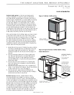
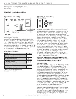
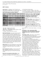
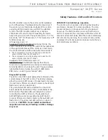
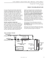
Figure 17: LT1 Limit Setting
CXM PCB
LT1
LT2
JW3-LT1 jumper should
be clipped for low
temperature operation
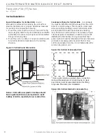
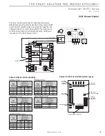
Electrical - Low Voltage Wiring
Accessory Connections
A terminal paralleling the compressor contactor coil
has been provided on the CXM/DXM control. Terminal
“A” is designed to control accessory devices, such as
water valves. Note: This terminal should be used only
with 24 Volt signals and not line voltage. Terminal “A” is
energized with the compressor contactor. See Figure 18
or the specifi c unit wiring diagram for details.
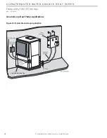
Figure 18: Accessory Wiring
Water Solenoid Valves -
An external solenoid valve(s)
should be used on ground water installations to shut off
fl ow to the unit when the compressor is not operating.
A slow closing valve may be required to help reduce
water hammer. Figure 18 shows typical wiring for a 24VAC
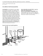
external solenoid valve. Figures 19 and 20 illustrate
typical slow closing water control valve wiring for Taco
500 series (ClimateMaster P/N AVM) and Taco SBV
series valves. Slow closing valves take approximately
60 seconds to open (very little water will fl ow before 45
seconds). Once fully open, an end switch allows the
compressor to be energized. Only relay or triac based
electronic thermostats should be used with slow closing
valves. When wired as shown, the slow closing valve will
operate properly with the following notations:
1. The valve will remain open during a unit lockout.
2. The valve will draw approximately 25-35 VA through
the “Y” signal of the thermostat.
Note: This valve can overheat the anticipator of an
electromechanical thermostat. Therefore, only relay or
triac based thermostats should be used.
Two-stage Units
Tranquility
®
30 (TT) two-stage units should be designed with
two parallel valves for ground water applications to limit
water use during fi rst stage operation. For example, at 1.5
gpm/ton [2.0 l/m per kW], a TT049 unit requires 6 gpm [23
l/m] for full load (2nd stage) operation, but only 4 gpm [15
l/m] during 1st stage operation. Since the unit will operate
on fi rst stage 80-90% of the time, signifi cant water savings
can be realized by using two parallel solenoid valves with two
fl ow regulators. In the example above, stage one solenoid
would be installed with a 4 gpm [15 l/m] fl ow regulator on
the outlet, while stage two would utilize a 2 gpm [8 l/m] fl ow
regulator. When stage one is operating, the second solenoid
valve will be closed. When stage two is operating, both
valves will be open, allowing full load fl ow rate.
Figure 21 illustrates piping for two-stage solenoid valves.
Review fi gures 21-23 for wiring of stage one valve. Stage
two valve should be wired between terminal “Y2” (ECM
board) and terminal “C.” NOTE: When EWT is below
50°F [10°C], 2 gpm per ton (2.6 l/m per kW) is required.
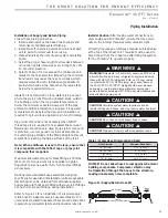
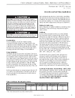
Low Voltage VA Ratings
Component
VA
Typical Blower Relay
6 - 7
Typical Reversing Valve Solenoid
4 - 6
30A Compressor Contactor
6 - 9
Subtotal
16 - 22
+ CXM board (5 - 9 VA)*
21 - 31
Remaing VA for Accessories
19 - 29
+ DXM board (8 - 12 VA)*
24 - 34
Remaing VA for Accessories
41 - 51
*Standard transformer for CXM board is 50VA.
Optional DXM board and/or DDC controls
include 75VA transformer.


