


3
c l i m a t e m a s t e r. c o m
T H E S M A R T S O L U T I O N F O R E N E R G Y E F F I C I E N C Y
Tr a n q u i l i t y
®
3 0 ( T T ) S e r i e s
R e v. : 0 7 / 1 8 / 1 3
026 = “E, F, G, H”
072 = “F, G, H”
038 = “F, G, H”
049 = “F, G, H”
064 = “F, G, H”
}
A
0 2 6
C
G
1
0
A L K
4 5 6
7
8
9
10
11
12
13
14
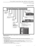
UNIT SIZE
RETURN AIR FLOW CONFIGURATION
VOLTAGE
CONTROLS
REVISION LEVEL
HEAT EXCHANGER OPTIONS
SUPPLY AIR FLOW &
MOTOR CONFIGURATION
TT
1 2
TT = Tranquility
®
Two Stage Scroll
SERIES
V
3
V = Vertical Up
CONFIGURATION
Standard
Motorized Valve
Non Coated Air Coil
Copper Cupro-Nickel Copper Cupro-Nickel
C
T
N
S
A
U
J
W
L = Left Return
R = Right Return
0 = None
WATER CIRCUIT OPTIONS
2 = HWG (Coil Only)
6 = HWG (Coil Only) w/Auto Flow Regulator 2.5 GPM/Ton
7 = HWG (Coil Only) w/Auto Flow Regulator 3.0 GPM/Ton
8 = Auto Flow Regulator 2.5 GPM/Ton
9 = Auto Flow Regulator 3.0 GPM/Ton
S
15
S = Standard
STANDARD
H = Horizontal
D = Vertical Down
5 = Internal Secondary Pump
Supply Configuration
Motor
K
TTV
N
TTD
P
TTH
W
TTH
Top
Down
Back
Straight
ECM
ECM
ECM
ECM
ClimaDry
®
E
P
D
F
Tin Plated Air Coil
D = DXM
L= CXM w/LON
M = DXM w/LON
P = DXM w/MPC
B = DXM
K = DXM w/LON
S = DXM w/MPC
w/
Disconnect
C = CXM
N = CXM w/MPC
A = CXM
E = CXM w/LON
R = CXM w/MPC
G = 208-230/60/1
H = 208-230/60/3
E = 265/60/1
F = 460/60/3
Cabinet Insulation
OPTION
1
A
J
K
2
C
L
M
3
E
N
P
1” FILTER
RAIL
RANGE
ULTRA
QUIET
2” FILTER
RAIL
1” FILTER
FRAME
2” FILTER
FRAME
4
G
R
S
NO
YES
NO
YES
YES
YES
YES
YES
NO
NO
NO
NO
NO
NO
YES
YES
YES
YES
NO
NO
NO
NO
NO
NO
YES
YES
YES
YES
NO
NO
NO
NO
NO
NO
YES
YES
YES
YES
NO
NO
NO
NO
NO
NO
B = Current 026, 049 - 072
C = Current 038
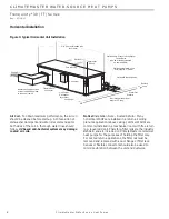
Model Nomenclature
Note: Above model nomenclature is a general reference. Consult individual engineering guides for
detailed information.
ClimaDry
®
II Option Notes:
1. Unit must have DXM control option. 460 volt unit units require a four wire power supply with neutral.
2. ClimaDry
®
II may not be combined with motorized water valve, internal secondary circulating pump, or automatic
fl ow regulator options.
3. Unit minimum entering air temperature while in the dehumidifi cation, cooling, or continuous fan modes is
70ºF DB/61ºF WB
. Operation below this minimum may result in nuisance faults.
4. A thermostat with dehumidifi cation mode or thermostat and separate humidistat/dehumidistat is required for
activation and control of ClimaDry
®
II.
5. Downfl ow and 575 volt units are not eligible for ClimaDry
®
II.


