background image

  Re motely Ad just able Dual- Zone Piezo Sen sor  

Mount this sensor in the passenger compartment, not in the engine compartment.
1. Firmly mount the sensor near the base of the steering column (if the steering column has a 

rotating sleeve, firmly screw the sensor to the interior firewall, kick panel or trunk wall). 

2. Mate the sensor to the connector with the BLACK, RED, and WHITE/BLUE wires.

3. After power-up, adjust the sensor as noted on page 15.

  Glass Tam per ing Sen sor  

Mount this sensor in the passenger compartment, not the engine compartment.
1. Mount the microphone holder so that it points into the passenger compartment, but will

not be exposed to direct sunlight.

2. Plug the microphone into the sensor (an optional second microphone can be added for

vans and other large vehicles for increased sensitivity and better discrimination).

3. Mate the sensor to the connector with the BLACK, RED and ORANGE wires.

  Aux il iary A with Se lecta ble Out put Type with AutoAc ti va tion  

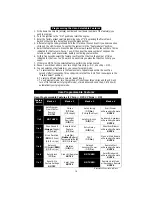
The Auxiliary A output (GRAY/VIOLET wire) can be programmed as either pulsed, latched

or timed and can be programmed to operate only when the system is disarmed (e.g., for use as

a remote trunk release). Note that the selectable output type is only programmable using the

CliffNet Wizard Pro. Auxiliary A output is activated by pressing the  button on the

companion remote control or button 2 on the master remote control. The factory setting is

pulsed output (1 second ground). The latched output stays at ground until the  button or

button 2 is pressed a second time, and the timed output stays at ground for any selected

duration between one second and four minutes. Current is limited to 0.15 amp. You can also

set this output to automatically activate every time the system is remotely-armed (perfect if

wiring as a timed output to close the electric windows and sunroof on European vehicles that

have an all-close feature). See 

Installer-Programmable Features

 on page 17 to change the type

of output,  set AutoActivation and/or disable operation while the system is armed.

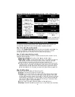
Euro pean Ve hi cle Win dow/Sun roof All-Close  

If the door key can close the power windows/sunroof, you can make them automatically close

upon remote arming (CliffNet Wizard is required to program this feature):
1. Find the wire that shows +12V or ground when the key is held to lock in the door cylinder.

2. Tap a wire in to this wire and connect to terminal 30 of the relay.

3. If the wire shows (-) when the key is turned, connect terminal 87 to (-). If the wire shows

+12V when the key is turned, connect terminal 87 to 12V.

4. Connect the output of the alarm that can be set to AutoActivate to terminal 85.

5. C12V to terminal 86.

8. Turn on the 

AutoActivate timed accessory upon remote arming

 feature as noted in the

installation manual for the alarm under Installer-Programmable Features.

8. Set the timer duration to proper time interval with two seconds added to that time

interval.En gine Bay Con nec tions.

9. Set Auxiliary Output A to 

Timer

 using the CliffNet Wizard.

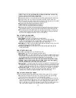
En gine Com part ment Con nec tions

  Hood Trig ger  

Vehicles with a ground-switching hood pin switch interface directly with ACE 7500 (on positive

switching Rolls-Royce vehicles, use a relay to invert polarity). If a switch cannot be located, you

must add a pin switch in a location away from water channels.
1. Connect the WHITE/BLACK wire to the hood pin wire.

12

Содержание ACE 7500

Страница 1: ......

Страница 2: ...Deterrent Bypass 10 Reverse Lights 10 Brake Lights 10 Manual Transmission 10 Diesel Engine 10 RPM Monitoring 11 Trunk Trigger 11 Remotely Adjustable Dual Zone Piezo Sensor 12 Glass Tampering Sensor 12...

Страница 3: ...ed Electronic Timer oTurbo Timer Output oDataPort Accessory Interface oHigh Output Insignia Siren oEight Event TotalRecall oPrewired LED Sensor Extended Range Receiver and PlainView 2 Switch Connector...

Страница 4: ...icing or operation 9 DO NOT mount any Clifford sensor in the engine compartment 10 Follow the system s Sequence of Installation to ensure proper installation and testing 11 Place the owner s manual in...

Страница 5: ...l side ignition and relay shown if manual transmission 4 Red Battery with 30 amp fuse 5 Red Battery with 20 amp fuse 6 Brown Parking light output 7 White Green Key side starter input 8 Orange Accessor...

Страница 6: ...lete 2 Plug the 18 CliffNet DataPort Extension Cable into the control unit Make sure the receptacle end will be accessible after the dash has been put back This eases later service 3 Plug the extended...

Страница 7: ...ou may find two wires in the steering column wireloom that test this way If so see the Secondary Ignition or Heater AC wire section below 2 Start the engine then cut the ignition wire The engine shoul...

Страница 8: ...y 2 Verify there is adequate space behind the selected location to accommodate the switch 3 Drill a 5 16 8mm mounting hole then insert the wires through the hole 4 Mate the switch s locking connectors...

Страница 9: ...make the connections shown in Diagram 4 for reverse polarity b If there are three wires proceed to step 2 c If the vehicle is a Nissan and it does not have a door lock switch find the single wire in t...

Страница 10: ...hows 12v when the parking lights are on and 0 volts when they are off 4 Connect both of the BROWN wires to the parking light wires 5 Connect the RED 18AWG wire from the 12 pin connector to the vehicle...

Страница 11: ...a 3 amp diode terminal 30 of an optional relay as shown on pages 4 5 and connect it into the BLUE WHITE brake input wire See also Manual Transmission section below 1 Turn the ignition ON and press th...

Страница 12: ...to all the other is the negative side and can be tested as described in step 2b above Installation Options 1 Installation Option 1 Negative Coil Connect the BLACK GRAY wire to the negative terminal of...

Страница 13: ...lected duration between one second and four minutes Current is limited to 0 15 amp You can also set this output to automatically activate every time the system is remotely armed perfect if wiring as a...

Страница 14: ...tly enter the disarmed state MANDATORY RPM PROGRAMMING NOTE ACE 7500 will not operate properly without this programming step NOTE If working on a diesel engine vehicle you must first set the system fo...

Страница 15: ...button The master remote control can operate higher level functions such as sensor adjustment by shifting the 4 buttons up to a higher level via the LevelShift button on the side of the remote contro...

Страница 16: ...erclockwise to decrease sensitivity clockwise to increase you may also reposition the sensor s microphone s Eight Event TotalRecall The system s nonvolatile memory records the identity of the last eig...

Страница 17: ...seconds after five seconds three chirps indicate that the ACE 7500 is now back in the Feature Select position b To select a different feature column repeat step 5 c To exit program mode turn the ignit...

Страница 18: ...system Select the row and column number then transmit the unused button channel on the other remote that you want to perform that function The system will respond with the same number of chirps as th...

Страница 19: ...on to the ON position nEngine does not respond This is the correct response proceed to step 3 nEngine starts or cranks The starter ignition fuel pump or immobilization circuits have been miswired Care...

Страница 20: ...tep 5 Test the door locks Arm the system by pressing button 1 on the remote control nDoors lock This is the correct response proceed to step 6 nDoors do not lock You either selected the wrong lock dia...

Страница 21: ...wait 10 seconds then thump the car softly with your fist n5 chirp warning tone Proceed to the next test Thump firmly nAlarm triggers Proceed to step 9 Adjust the sensor as needed Step 10 Test the Gla...

Страница 22: ...orking properly and when open is consistently showing less than 1 5 volts If not the hood pin switch must be thoroughly cleaned or replaced Step 15 Test the AutoArming feature Turn the ignition ON sta...

Страница 23: ...not crank or grind Push the brake pedal and turn the ignition OFF Press button 4 again to start the vehicle nTest 5 Leave the engine running It should turn itself off after 30 minutes If the system d...

Страница 24: ......

Отзывы: