6
SERVICE INSTRUCTIONS
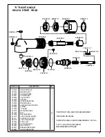
When installing needle bearings, press only on the bear-
ing's stamped end. The pinion needle bearing should be
slipped on the pinion gear and pressed into the housing to
the following depth:
''V" Right Angle Head = 3/16" (81mm)
"X" Right Angle Head = 3" (76.2mm)
The pinion bearing retainer, No. 869877, should be securely
tightened to ensure proper gear make-up.
The driven gear bearing cap should be torqued to 100/110
ft.-lb. (135/149Nm) and the bearing cap lock screw torqued
to 10 in.-lb. (1.13Nm) minimum. Note: When assembling the
angle head to the complete tool, the clamp nut, No. 869878,
(left hand threads) must be torqued to 100/110 ft.-lb. (135/
149Nm).
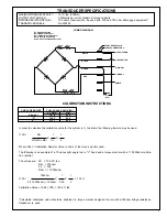
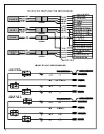
Transducer Wiring Connection
NOTE: Do not bend, strike, push or pull the transducer on
the plastic coated area of the transducer. Connect the cable
connector, No. 202183, to the transducer and wrap the
wiring around the transducer until the cable connector is one
(1) wrap past the connection and then thread the connector
thru the hole in the transducer. Install the transducer in the
motor housing, feeding the connector thru the hole in the
housing. Line up the pins on the transducer with the grooves
in the housing being careful not to pinch the connector.
Safety Check
After repair or replacement of parts, tools equipped with an
automatic shut-off device should be tested to verify that it is
functioning properly. The torque setting entered into the
torque control monitor must not exceed maximum torque
range or tool will stall and not shut-off.
REASSEMBLY — GENERAL
The tool is reassembled in the reverse order of disassembly.
Clean all parts thoroughly in solvent and inspect for damage
or wear. Check all bearings for wear which can be detected
by excessive end play and/or roughness which would indi-
cate a brinelled condition. The rotor blades should be
replaced at every repair cycle if they measure less then 3/
8" (9.5mm) at either end. All gear teeth, bearings, and pins
should receive a close inspection and be replaced if neces-
sary.
NOTE: During reassembly of the complete tool, it is important
that the motor be free. After the tool is completely assembled,
the right angle square drive spindle should turn freely using
a small hand wrench. If the spindle does not turn freely, the
motor should be checked for proper spacing. Do not run the
tool until the spindle turns freely. Failure to do this could result
in damage to motor components.
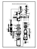
Motor Unit
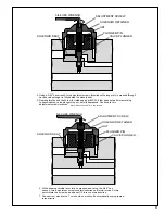
Install the rear rotor bearing into the rear bearing plate. Make
sure the outer bearing race is firmly seated in bearing plate.
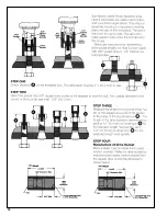
Clamp the rotor lightly in the vise with the threaded end up and
slip the rear bearing plate assembly onto the rotor shaft far
enough for the bearing lock nut to start. Tighten the lock nut
until there is approximately .0015" clearance between the
rotor and bearing plate. The outer bearing race should be
firmly seated and the rotor held forward when checking this
clearance. Pack both rotor bearings with a good grade of No.
2 Moly grease after assembly of the motor unit.
Right Angle Head
Replace blade if less than
3/8" (9.5mm) on either end.
SOFT
JAWED
VISE
.0015"
Clearance
Содержание 75NLTVCE Series
Страница 18: ...18...
Страница 19: ...19 NOTES...
Страница 20: ...20 670 Industrial Drive Lexington SC 29072 Phone 803 359 1200 Fax 803 359 2013...

