5
suitable driver, drive the pinion gear out of the right angle
housing.
Gear Train - 2, - 3, - 4, - 6, & - 10
Important: Do not bend, strike, push or pull in any way that will
cause strain in the plastic coated area of the transducer.
Remove the gear train from the front of the ring gear. Remove
the retainer ring 869634 and drive bearing 847566 out of
transducer. Drive roll pin, No. 812164, out of ring gear and
transducer into the bearing bore. Slip ring gear off transducer.
Gear Train - 7
Important: Do not bend, strike, push or pull in any way that will
cause strain in the plastic coated area of the transducer.
Remove the gear train from the front of the ring gear. Remove
the retainer ring 869634 and drive bearing 847566 out of
transducer. Drive roll pin, No. 812164, out of ring gear and
transducer into the bearing bore. Slip ring gear off transducer.
Line the idler gears up with the pockets machined in the ring
gear. Slip the spider assembly out the rear of the ring gear.
Motor Unit
Clamp the cylinder lightly in the vise with the hex end of the rotor
up. Note: Rotor pinion No.867524, used on the - 4 and - 6 stall
models should be removed at this time. Drive the rotor out of the
front rotor bearing, No. 619377. Be careful not to damage the
rotor. The front bearing plate, No.867536, cylinder, and rotor
blades, No.203219, can now be removed from the rotor. Clamp
the rotor in the vise with the rear bearing plate up. After
unscrewing the bearing lock nut, No. 865352, the rotor can be
driven out of the rear rotor bearing.
Motor Housing
Clamp the flats of the motor housing in the vise and use a strap
wrench to unscrew the handle, No.202182. Disconnect the wire
bundle from the cable connector, No.202183. Remove retainer
ring, No. 203053, and slide the exhaust deflector off the rear of
the housing.
REASSEMBLY
The tool is reassembled in the reverse order of disassembly.
Clean all parts thoroughly in a solvent and inspect for damage
or wear. Check all bearings for wear which can be detected by
excessive end play and/or roughness which would indicate a
brinelled condition. The rotor blades should be replaced at every
repair cycle or if they measure less than 1/4" at either end. All
gear teeth, bearings, and pins should receive a close inspection
and be replaced if necessary.
To assemble the motor, install the rear rotor bearing into the rear
bearing plate. Make sure the outer bearing race is firmly seated
in the bearing plate. Clamp the rotor body lightly in the vise with
the threaded end up and slip the rear bearing plate assembly
onto the rotor shaft far enough for the bearing lock nut to start.
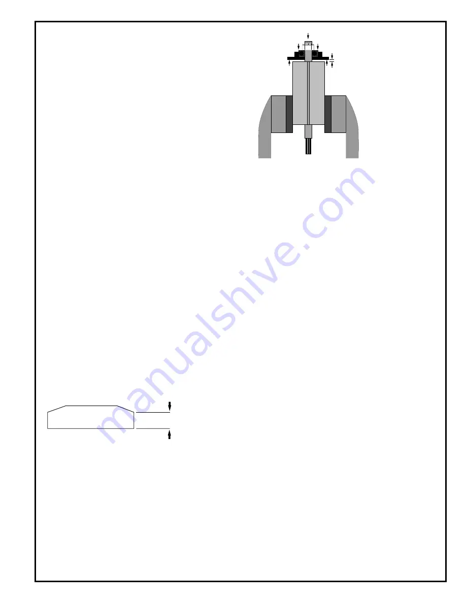
Tighten the lock nut until there is approximately .0015" clear-
ance between the rotor and bearing plate. The outer bearing
race should be firmly seated and the rotor bumped forward when
checking this clearance. Pack both rotor bearings with a good
grade of NLGI 2-EP grease after assembly of the motor unit.
Note: During reassembly of the complete tool, it is important
that the motor be free. After the tool is completely assembled,
the right angle square drive spindle should turn freely using a
small hand wrench. If the spindle does not turn freely, the motor
should be checked for proper spacing. Do not run the tool until
the spindle turns freely. Failure to do this could result in damage
to motor components.
Gear Train - 7
When installing the spider assembly the idler gears must be
aligned with the pockets machined in the ring gear. Line up the
hole in the ring gear with the hole in the transducer and install
the pin, No.812164.
Transducer Wiring Connection
Note: Do not bend, strike, push or pull in any way that will cause
strain in the plastic coated area of the transducer. Connect the
cable connector, No. 202183, to the transducer and wrap the
wiring around the transducer until the cable connector is one (1)
wrap past the connection and then thread the connector thru the
hole in the transducer. Install the transducer in the motor
housing, feeding the connector thru the hole in the housing. Line
up the tangs on the transducer with the grooves in the housing
being careful not to pinch the connector.
Right Angle Head
During reassembly of the gear train and angle head, all of the
various gears and bearings should receive a generous amount
of NLGI 2-EP grease. The pinion needle bearing should be
slipped onto the pinion gear and then pressed into the right
angle housing until the rear of the bearing is flush or slightly
below the step in the housing. Note: During reassembly of the
T right angle head, the bearing cap, No.867509, should be
torqued to 10010 ft. - lb. Also, the bearing cap lock screw, No.
867997, should be torqued to 10 in. Ib. minimum.
Pour a few drops of 10W machine oil into the air inlet after
complete assembly to ensure immediate lubrication of all motor
parts when air is applied.
SAFETY CHECK
After repair or replacement of parts, tools equipped with an
automatic shutoff device should be tested to verify that they are
functioning properly.
TRIP ROD SIZING — JOINT RATE ONLY
If the trip rod requires replacement the new one must be sized
to 4.660".
SOFT
JAWED
VISE
.0015"
Clearance
Must be replaced if
7/32" (5.6mm) or less
at either end.
Содержание 55NJLT
Страница 19: ...19...
Страница 20: ...20 670 Industrial Drive Lexington SC 29072 Phone 803 359 1200 Fax 803 359 2013...


