Cleco 48E***P Series Скачать руководство пользователя страница 16

16

P2144BA/EN 2014-08

2144b-en_1_5_bedingt.fm, 09.09.2014
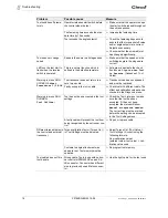
Troubleshooting

8

Tool switches off prema-
turely

Operator releases start switch before 
the control stops the tool

Make sure that the operator keeps 
the start switch pressed throughout 
the entire sequence.

The fastening time exceeds the stan-
dard time by 10 seconds.

Increase the fastening time

Tool exceeds the angle setpoint

Check the fastening sequence to 
ensure that the torque shutoff value 
and/or angle setpoint are correct. 
Adjust as necessary.

Check whether the screwed joint 
has changed significantly.

Tool does not change 
speed

Speed is the same in all stages used

Make sure that the speed and the 
switching angle in the stages are 
correct.

LEDs on the tool start to 
flash when the reverse 
switch is operated.

This is a normal function which is 
defined in the default parameters. 

Activate or deactivate the check 
box 

Blink Lights when Tool 

in Reverse 

(

Advanced > Tool 

Setup

)

Warning in menu 

RUN 

SCREEN

Offset 

Transducer 1/2 NOK

The transducer does not return to a 
zero torque vale

Transducer has been overloaded 
and must be replaced

Faulty wiring in tool or in cable

Check tool with different cable. The 
offset and calibration values can be 
checked in the 

Diagnosis

 menu. 

Warning in menu

 RUN 

SCREEN

:

Tool Offline!

Tool has not been accepted in the 

tool 

settings

Check the Tool List menu to make 
sure that the tool has been 
accepted. If it has not been 
accepted, the status will show 

Manual acceptance needed

The correct line must be marked 
before the setting can be accepted 
in the 

Tool Settings

 menu.

A faulty cable will prevent the tool from 
being recognized by the nutrunner con-
trol

Repair or replace cable

Different torque display in 
the control and external 
transducer

Torque calibration factor (Torque Cal.) 
in 

Tool Settings

 must be adjusted.

Adjust Torque Cal. (T

ool Setup > 

Tool Settings > Accept) 

using the 

following formula:
New calibration value = 
(external value / tool value) × cali-
bration value used

Customer's angle attachment was 
added to tool. Tool memory must be 
updated. 

Reprogram tool memory

Tool cable does not fit in 
tool handle

Wrong cable. Tools in use with nutrun-
ner control mPRO400GC use an Air-
LB connector. Connector has different 
size to previously used Matrix connec-
tor.

Use the right cable for the tool used

Problem

Possible cause

Measure

Содержание 48E***P Series

Страница 1: ...For additional product information visit our website at http www apextoolgroup com 48EAE P Electric hand held nutrunner Instruction Manual P2144BA EN 2014 08 ...

Страница 2: ...ts out options Nomenclature Symbols in the text 48 E A E P Series Square version 48 4 1 2 3 3 8 6 3 4 Motor E Electric motor brushless Output version P Pin Tool version A Angle Max torque Property 1 38 38 Nm E Air LB connector 51 51 Nm 61 61 Nm 85 85 Nm 120 120 Nm 175 175 Nm 230 230 Nm italics Identifies menu items such as Diagnosis Identifies the selection of a menu item from the menu such as Fil...

Страница 3: ...t or the product without prior notice This document may not be reproduced in whole or in part in any way shape or form or copied to another natural or machine readable language or to a data carrier whether electronic mechanical opti cal or otherwise without the express permission of Apex Tool Group Identifies movement in one direction Identifies function and force ...

Страница 4: ...4 P2144BA EN 2014 08 2144a en_Deckblatt fm 09 09 2014 ...

Страница 5: ...escription 11 4 2 Operation and functional elements 12 5 Accessories 13 6 Initial Operation 13 6 1 Use of reaction bar 13 6 2 Carrying out rundown 13 7 Servicing 14 7 1 Service schedule 14 7 2 Lubricants 14 7 3 Prevent uncontrolled electrostatic discharge 15 8 Troubleshooting 15 9 Spare parts 17 9 1 Handle 18 9 2 Motor 20 9 3 2 stage gearing 22 9 4 2 stage gearing 24 9 5 3 stage gearing 26 9 6 Ang...

Страница 6: ...6 P2144BA EN 2014 08 P2144BA EN_2014 08_48EAE_P3_P4IVZ fm 09 09 2014 12 Disposal 32 ...

Страница 7: ...h the word WARNING warns of a potentially dangerous situation for the health of personnel If this warning is not observed death or serious injury may occur CAUTION A symbol combined with the word CAUTION warns of a potentially harmful situation for the health of personnel or damage to property or the environment If this warning is not observed injuries property or environmental damage may occur Th...

Страница 8: ... not misuse cable to carry or suspend the electric tool or to pull the plug from the connector socket Keep the cable away from heat oil sharp edges or mov ing parts of the machine Damaged or tangled cables will increase the risk of an electric shock The following instructions help prevent short circuits Ensure that the PE connection is of low resistance Use a mains transformer for cable lengths in...

Страница 9: ...ric tools accessories insertion tools etc in accordance with these instructions Take into account the work conditions and the job to be done The use of electric tools for applications other that those intended can lead to a danger ous situation General Safety Instructions for Electric Tools Service a Only have your electric tool repaired by a qualified specialist and only using origi nal spare par...

Страница 10: ...ion with a control and tool cable supplies by Apex Tool Group Do not use as a hammer or for re bending Do not open it or modify it structurally Do not use it in areas where there is a risk of explosion 1 5 Standards 1 5 1 EMC Industrial environment EMC limit class A The tool complies with the following EMC standards EN 55011 2007 EN 61000 6 2 2005 1 6 Noise and Vibration Sound pressure Lp 70 dB A ...

Страница 11: ...uct Description 4 1 General Description Sturdy brushless motor with resolver Shutoff is torque angle controlled Integrated preamplifier including service memory Self identification of tool when connected to controller LED display provides information about current rundown result Clockwise counterclockwise rotation Fastening parameters are set via the controller Data is transmitted and power suppli...

Страница 12: ...n Start rundown 4 2 3 Reverse switch The reverse switch changes the rotation direction of the 48EAE Turn reverse switch as far as it will go Clockwise rotation for screwing in screws Counterclockwise rotation for loosening or screwing out screws LED Operating status Green continuous light OK Red continuous light NOK Yellow Enable 2 4 1 3 Item Designation 1 Illuminated ring LED display 2 Connection...

Страница 13: ...ept recognized values on the control in Tool Setup Tool Settings Accept Adjust torque and speed as necessary Make sure that the reverse switch is in the correct position Fit the bit and press the Start button to start the rundown If the tool switches off release the Start button Tool holder Order no 941293 1 set 2 V shape Start lever extension Order no S387710 Tool cable Refer to product catalog P...

Страница 14: ...to DIN 51502 ISO 3498 CAUTION Danger of injury through unintentional activation prior to servicing 48EAE disconnect power supply Fastening Cycles1 1 For number of fastening cycles see Dynamic Service Counter of controller Measures 100 000 Check the tool components for tight fit Check the tool and tool cable for damage Check the gearing and angle attachment for leaks 250 000 Clean gearing parts wit...

Страница 15: ...d Deactivate Tool Enable Advanced Tool Setup Faulty cable Repair or replace cable Bent pins in the cable or tool Straighten contact pins or replace faulty connector Self identification data not recognized after tool change Accept Data again Tool Setup Tool Settings Accept No acoustic signal after connection of tool cable Software incorrect Check controller software measur ing board software Cable ...

Страница 16: ...as been overloaded and must be replaced Faulty wiring in tool or in cable Check tool with different cable The offset and calibration values can be checked in the Diagnosis menu Warning in menu RUN SCREEN Tool Offline Tool has not been accepted in the tool settings Check the Tool List menu to make sure that the tool has been accepted If it has not been accepted the status will show Manual acceptanc...

Страница 17: ...arts 9 9 Spare parts Always use only original Cleco spare parts Failure to comply with this instruction can result in decreased performance and an increased need for maintenance Installing spare parts from other man ufacturers will void all manufacturer s warranties ...

Страница 18: ...18 P2144BA EN 2014 08 2144d en_Ersatzteile fm 09 09 2014 Spare parts 9 9 1 Handle Models 48EA E 38 48EA E 51 48EA E 61 48EA E 85 48EA E 120 48EA E 175 48EA E 230 ...

Страница 19: ...2144d en_Ersatzteile fm 09 09 2014 P2144BA EN 2014 08 19 Spare parts 9 1 Order no 2 Quantity 3 Recommended spare part for every 1 5 tools 4 Dimension ...

Страница 20: ...14 08 2144d en_Ersatzteile fm 09 09 2014 Spare parts 9 9 2 Motor Transducers cannot be exchanged see 11 Recalibration page 31 11 12 Models 48EA E 38 48EA E 51 48EA E 61 Models 48EA E 85 48EA E 120 48EA E 175 48EA E 230 ...

Страница 21: ...9 2014 P2144BA EN 2014 08 21 Spare parts 9 1 Order no 2 Quantity 3 Recommended spare part for every 1 5 tools 4 Dimension TAB 9 2 Index 48EA E 38 48EA E 51 48EA E 61 48EA E 85 48EA E 120 48EA E 175 48EA E 230 2 3 8 207340 207341 1 ...

Страница 22: ...22 P2144BA EN 2014 08 2144d en_Ersatzteile fm 09 09 2014 Spare parts 9 9 3 2 stage gearing See 7 2 Lubricants page 14 Models 48EA E 38 48EA E 51 48EA E 61 ...

Страница 23: ...2144BA EN 2014 08 23 Spare parts 9 1 Order no 2 Quantity 3 Recommended spare part for every 1 5 tools 4 Dimension TAB 9 3 Index 48EAE38P3 48EAE51P3 48EAE61P3 6 541894 17 541897 20 541897 20 11 542230 542233 542233 12 542079 542099 542099 ...

Страница 24: ...24 P2144BA EN 2014 08 2144d en_Ersatzteile fm 09 09 2014 Spare parts 9 9 4 2 stage gearing See 7 2 Lubricants page 14 Models 48EA E 85 48EA E 120 ...

Страница 25: ...09 09 2014 P2144BA EN 2014 08 25 Spare parts 9 1 Order no 2 Quantity 3 Recommended spare part for every 1 5 tools 4 Dimension TAB 9 4 Ref 48EA E 85 48EA E 120 9 1 542333 1 542332 11 3 541474 17 3 541475 21 13 1 541279 1 541278 ...

Страница 26: ...26 P2144BA EN 2014 08 2144d en_Ersatzteile fm 09 09 2014 Spare parts 9 9 5 3 stage gearing See 7 2 Lubricants page 14 Models 48EA E 175 48EA E 230 ...

Страница 27: ...9 09 2014 P2144BA EN 2014 08 27 Spare parts 9 1 Order no 2 Quantity 3 Recommended spare part for every 1 5 tools 4 Dimension TAB 9 5 Ref 48EA E 175 48EA E 230 15 1 542327 1 542331 17 3 541472 14 3 541473 17 19 1 542531 1 542478 ...

Страница 28: ...21PT 48EAE51P3 AE51P3 937026PT 48EAE61P3 AE61P3 937031PT 48EAE85P4 AE85P4 937776PT 48EAE120P4 AE120P4 up to serial no 709579 936907PT from serial no 709580 937786PT 48EAE175P6 AE230P6 942073PT 48EAE230P6 48EA E 38 48EA E 51 48EA E 61 48EA E 85 48EA E 120 48EA E 175 48EA E 230 1 2 1 Order no 2 Quantity 3 Recommended spare part for every 5 tools 4 Dimension Is provided and adjusted by user see 6 1 U...

Страница 29: ...2144g en_TechnDaten fm 09 09 2014 P2144BA EN 2014 08 29 Technical data 10 10 Technical data 10 1 Dimensions 48EAE51P3 48EAE61P3 48EAE38P3 ...

Страница 30: ...30 P2144BA EN 2014 08 2144g en_TechnDaten fm 09 09 2014 Technical data 10 48EAE175P6 48EAE230P6 48EAE120P4 48EAE85P3 ...

Страница 31: ...nter if necessary The machine capability can only be ensured through dynamic calibration We document the data in an updated certificate Type Recommended torque range Idling speed Screw size 10 9 Weight Calibration data Torque nominal Angle pulses Resolver ft lbf Nm max ft lbf Nm min rpm mm kg Nm degrees 48EAE38P31 1 on request 28 38 5 9 8 1175 M8 1 85 47 255 72 4181 48EAE51P31 37 6 51 8 1 11 835 M...

Страница 32: ...onment Catch auxiliary materials oils greases when drained and dispose of them properly Separate the components of the packing and segregate the different materials before disposing of them Follow the locally applicable regulations Observe generally valid disposal guidelines such as in Germany the Electrical and Electronic Equipment Act ElektroG Hand in the tool at your company collection point or...

Страница 33: ......

Страница 34: ...es Service Center 3990 East Market Street York PA 17402 USA Phone 1 717 755 2933 Fax 1 717 757 5063 France Apex Tool Group SNC 25 Rue Maurice Chevalier BP 28 77831 Ozoir la Ferrière Cedex France Phone 33 1 6443 2200 Fax 33 1 6440 1717 Mexico Apex Tool Group México S de R L de C V Vialidad El Pueblito 103 Parque Industrial 76220 Querétaro Mexico Phone 52 442 211 3800 Fax 52 442 103 0443 Lexington S...

Отзывы: