4
OFF
OPERATING INSTRUCTIONS
CLECOMATIC MODELS
Tools equipped with the CLECOMATIC clutch are designed to tighten the
fastener to a predetermined torque and shut off automatically. Releasing
the throttle lever will allow the tool to reset for the next cycle.
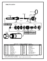
CLUTCH ADJUSTMENT
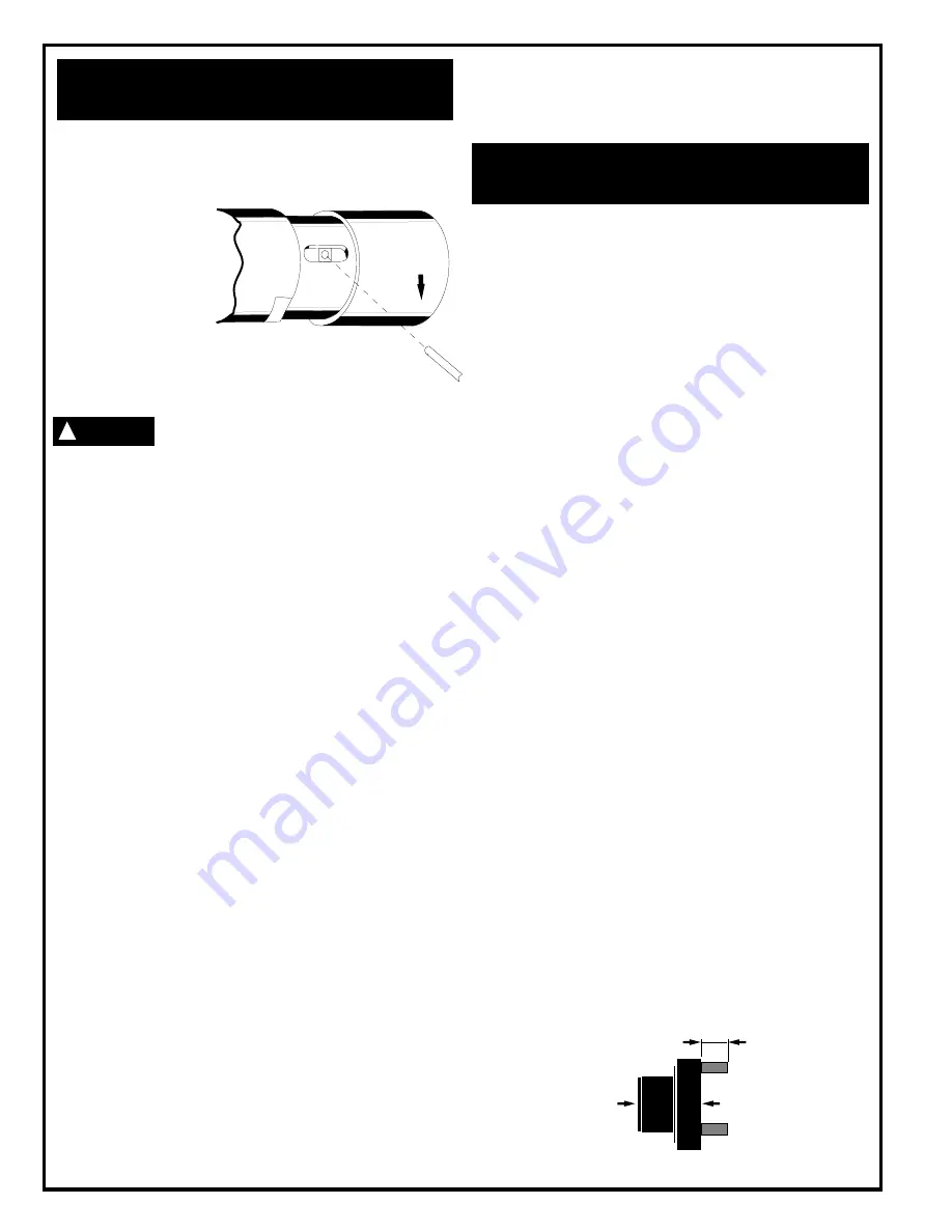
Shut off air supply to the tool
and rotate the adjustment
cover, No. 202829, 180° to
uncover the adjustment slot
in the clutch housing. Ro-
tate the spindle until the hole
in the adjustment nut is vis-
ible in the slot. Use a 1/8"
(3mm) diameter pin to hold the nut. Use a suitable tool to
turn the spindle in a counterclockwise direction to increase
torque or clockwise to decrease torque. Return the adjustment cover
to its closed position after every adjustment.
If the clutch is adjusted over the maximum power
output of the tool, the clutch will not function and the
tool will operate like a stall-type tool. Also, if the tool is being operated at
its upper torque limits, a drop in air pressure could cause the clutch not to
function due to a loss of motor power and the tool will function like a stall-
type tool. If tool stalls, operator must resist stall torque until the throttle is
released.
Operational check: Grip tool securely and be prepared to counteract stall
torque in case clutch is improperly adjusted. THIS IS A HIGH TORQUE
TOOL.
THROTTLE POSITION
"K" & "M" Right Angle Head
Both the "K" & "M" heads are threaded to the gear case. Throttle
positioning is accomplished by using shims between the head and the
gear case as required to properly position the throttle lever with respect to
the head to prevent hand entrapment. (See Torque Reaction page 2).
Retighten head with proper wrench to a torque higher than the torque rating
of the tool.
AIR SUPPLY
The tool is designed to operate at 90 psig (6.2 bar) air pressure. The air
pressure should be checked at the tool's air inlet while the tool is running.
For maximum performance, use a 5/16" I.D. air hose up to 8 feet in length.
If additional length is required, a 3/8" I.D. or larger hose should be
connected to the 5/16" I.D. hose.
LUBRICATION
An automatic in-line filter-lubricator is recommended as it increases tool
life and keeps the tool in sustained operation. The in-line lubricator should
be regularly checked and filled with a good grade of 10W machine oil.
Proper adjustment of the in-line lubricator is performed by placing a sheet
of paper next to the exhaust ports and holding the throttle open approxi-
mately 30 seconds. The lubricator is properly set when a very light stain
of oil collects on the paper. Excessive amounts of oil should be avoided.
Application of the tool should govern how frequently it is greased. It is
recommended that the idler gears and angle gears receive a generous
amount of NLGI 2-EP grease after 40 hours of operation.
Either the angle head or clutch housing, depending on the particular
model, must be removed (left hand threads) from the gear case and
grease applied through the hex in the gear spider to lubricate the idler
gears. Grease is applied to the angle gears through the grease fitting
located in the angle head housing. Use only a low pressure grease gun.
STORAGE
In the event that it becomes necessary to store the tool for an extended
period of time (overnight, weekend, etc.), it should receive a generous
amount of lubrication at that time and again when returned to service. The
tool should be stored in a clean and dry environment.
DISASSEMBLY-GENERAL (ALL MODELS)
Unscrew (left hand threads) and remove the right angle head. Remove pin
No. 884125 from the cable adapter No. 202880. Unscrew the inlet bushing
No. 202883 and remove exhaust deflector No. 202874 far enough to
unplug wiring. Unscrew throttle valve cap No. 832207. Remove throttle
valve spring No. 844060 and throttle valve No. 202884. Remove housing
shroud No. 203205 from rear of backhead No. 203188 very carefully to
prevent damage to the wiring. Unscrew (left hand threads) transducer
housing and lift carefully, feeding the wiring through the hole in the
backhead. Lift out transducer No. 202877, drive shaft and transducer
spacer No. 202881. To remove motor assembly tap backhead lightly on
a soft surface.
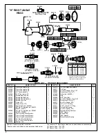
"K" RIGHT ANGLE HEAD DISASSEMBLY
To disassemble the right angle head, unscrew the spindle bearing cap.
This will permit the removal of the spindle assembly. The pinion bearing
retainer, No. 863564, may be removed by utilizing a 5/8" hex nut and a
5/8" deep socket. Drop the hex nut over the pinion shalt and engage the
hex in the bearing retainer and unscrew the retainer using the deep socket.
Unscrew the plug, No. 842366, and using a suitable driver, drive the pinion,
No. 202200, and related bearings out of the angle head.
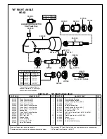
'M" RIGHT ANGLE HEAD DISASSEMBLY
Using a suitable spanner wrench, unscrew (left hand threads) the bearing
cap, No. 864396. Remove the spindle, ball bearing, No. 842517, and
driven gear by clamping the spindle in a vise and driving the right angle
housing, No. 869048, away from the spindle using a soft-faced mallet. The
ball bearing can now be removed by pressing the larger end of the spindle
through the bearing I.D. Press the smaller end of the spindle through the
gear to remove the driven gear. The pinion bearing retainer, No. 863564,
may be removed by utilizing a 5/8" hex hut and a 5/8" deep socket. Drop
the hex nut over the pinion shaft and engage the hex in the bearing retainer
and unscrew the retainer using the deep socket.
TRANSDUCER DISASSEMBLY
Remove the ring gear and transducer assembly from the rear of the
transducer housing. Press drive shaft No. 204196 or 204197, out of the
transducer bearing No. 847566. Remove the retainer ring No. 619017,
from the transducer and tap lightly on a soft surface to remove bearing, No.
847566. Drive the roll pin No. 202888, into the transducer until it falls inside
the transducer. Then remove the transducer from the rear of the ring gear.
Note: The transducer is a very delicate part and must be handled very
carefully.
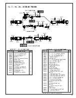
GEAR TRAIN DISASSEMBLY
Single Reduction
The spider should be pressed out the rear of the gear case, No. 202889.
Remove the retainer ring, No. 844364, and press the bearing, No. 847147,
out the front of the gear case.
If replacement of the idler gear pins is necessary, they should be pressed
out the rear of the spider. See Fig. 1 for replacement pin height.
Fig. 1 — Single Reduction Spider
CAUTION
!
SERVICE INSTRUCTIONS
.240
.255
Front
Rear
Содержание 35NALTV Series
Страница 14: ...14 NOTES...
Страница 15: ...15 NOTES...
Страница 16: ...16 670 Industrial Drive Lexington SC 29072 Phone 803 359 1200 Fax 803 359 2013...


