5
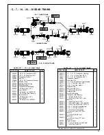
Double Reduction
Both spiders should be removed from the rear of gear case, No. 202875.
Remove the retainer ring, No. 844364, and press the bearing, No. 847147,
out the front of the gear case.
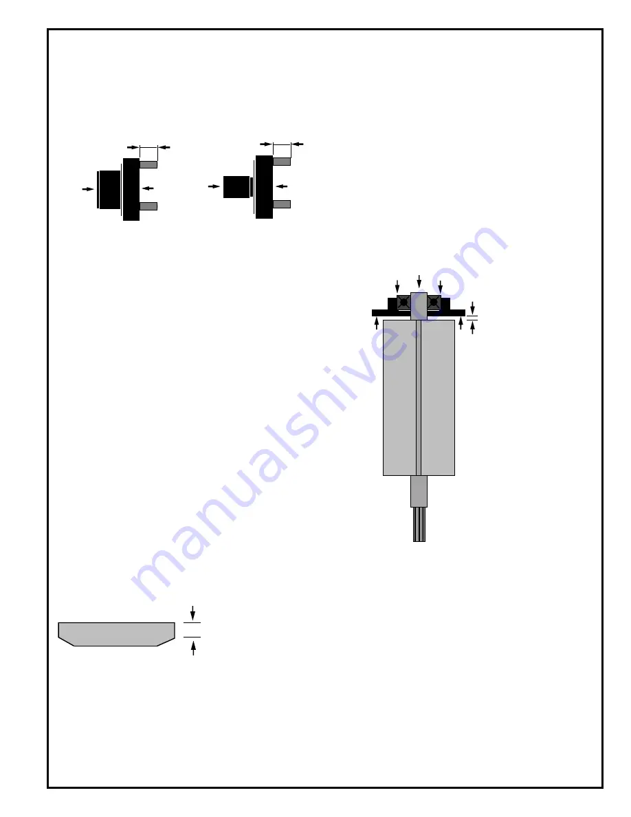
If replacement of the idler gear pins is necessary, they should be pressed
out the rear of the spider. See Fig . 2 for replacement pin height.
- 10 2nd Reduction Spider - 5, - 7 & - 10 1st Reduction Spider
Fig. 2 - Double Reduction Spiders
LIGHT RING KIT DISASSEMBLY
To remove light ring kit and housing shroud, loosen all three set screws
several turns. NOTE: Do not rotate the light ring kit or housing shroud when
removing from handle to prevent breaking wires. Hold pig tail connection
while removing light ring kit and housing shroud from handle.
MOTOR DISASSEMBLY
Use a soft-faced hammer to drive the rotor out of the front rotor bearing No.
619377. This will allow tPhe cylinder and five (5) rotor blades to be
removed from the rotor. Set the rear bearing plate on the vise jaws with the
rotor hanging down. Use a 7/32" punch to drive the rotor out of the rear rotor
bearing.
BACKHEAD DISASSEMBLY
Unscrew and remove the inlet bushing, No. 202883, for inspection and
cleaning of the air inlet screen, No. 833300. Replace the screen if clogged
or torn. The throttle valve and related components may be removed by
unscrewing the throttle valve cap, No. 832207. Remove flow valve, No.
203036, by removing retainer ring No.864271 and unscrewing with
screwdriver.
REASSEMBLY-GENERAL
All parts should be washed in a solvent and inspected for damage or wear.
Particular attention should be given to all bearings, gears, gear pins, and
rotor blades as failure of these parts could cause damage to more
expensive parts. Rotor blades should be replaced at each repair cycle or
if they measure less than 3/16"(4.7mm) on either end.
Inspect and replace any "O"-rings or seals that show signs of wear of
deterioration. All gears, gear pins, and open bearings should receive a
generous amount of NLGI 2-EP grease during reassembly.
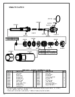
During reassembly of the clutch, all parts should receive a thin coating of
a mixture of 10W machine oil and NLGI 2-EP grease. Reassembly of all
of the various sub-assemblies is in the reverse order of disassembly;
however, the following paragraphs list some of the more important
reassembly procedures.
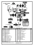
"K" RIGHT ANGLE HEAD REASSEMBLY
Slip pinion needle bearing No. 869864, (unstamped end first) on the pinion
No. 202200, and press (press on the bearing's stamped end) the bearing
to a depth of 7/8" from the face of the bearing bore. Install pinion ball
bearing No. 847846 and bearing retainer No. 863564, in the head and
tighten retainer securely using the 5/8" hex nut and 5/8" deep socket.
Using a suitable driver through the hole in the top of the head, drive the
pinion back to make sure it is seated properly in the head.
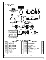
"M" RIGHT ANGLE HEAD REASSEMBLY
Assemble the spindle and related components in the head and securely
tighten (left hand threads) the bearing cap No. 864396. Use bearing
spacer No. 869050, to press the pinion needle bearing No. 863360, (press
on the bearing's stamped end) in the head. Install ball bearing No. 847846,
and bearing retainer No. 863564, in the head and tighten retainer securely
using the 5/8" hex nut and 5/8" deep socket.
MOTOR REASSEMBLY
Assemble the rear rotor bearing and rear bearing plate (press on the
bearing's inner race) onto the rear rotor shaft until there is approximately
.0015" clearance between the plate and rotor.
Assemble the five (5) rotor blades, cylinder, front bearing plate, and front
rotor bearing (press on the bearing's inner race) to the rotor assembly.
After final assembly, the cylinder should be held firmly, but not tightly
between the two (2) bearing plates and the rotor should turn freely and not
rub either bearing plate.
TRIP ROD SIZING
Install trip rod No. 202765 in tool. Place clutch assembly in the clutch
housing, making certain that the clutch seats against the spindle bearing.
Engage the clutch housing threads with the gear case. Depress the throttle
lever (with air supplied to the tool). If the motor runs at this point, remove
trip rod and shorten approximately 1/8". Reinstall, then with lever de-
pressed, slowly screw the clutch housing onto the gear case until the motor
just begins to start. At this point, release throttle lever and screw the clutch
housing down an additional one and a half turns. Measure the gap between
the clutch housing and shoulder of gear case. Cut this amount off the trip
rod.
SAFETY CHECK
After repair or replacement of parts, tools equipped with an automatic shut
off device should be tested to verify that the device is functioning properly.
.360
.375
Front
Rear
.240
.255
Front
Rear
.0015" (.038mm)
Clearance
Must be replaced if less than
3/16" (4.7mm) on either end.
Содержание 35NALTV Series
Страница 14: ...14 NOTES...
Страница 15: ...15 NOTES...
Страница 16: ...16 670 Industrial Drive Lexington SC 29072 Phone 803 359 1200 Fax 803 359 2013...


