


Casing Assembly
Model FLE Assembly
3-22
750-192
14. Install Inner Casing
NOTE:
DO NOT touch the insulation when you are
moving the panels. This can cause the insulation
to move and undo the work from step 13. Try not
to let the insulation touch the boiler until it is in its
resting position (Figure 3-56).
•
The inner casing panels are to be oriented so that the
two lift lugs are closer to the top
•
Panels should be installed starting in the middle.
Place the 1st (middle) panel on the base. Install a
washer and place the nuts (several turns) on the 2
nd
and 4
th
stud. Repeat this at the top of the panel.
•
Using the pipe dope, seal the seam of the gaskets at
the top and bottom of the center panel (Figure 3-57).
•
Install the next two panels by positioning them so
that the bottom of the panel is at the same level as
the middle panel. Angling it into position first rather
than setting the panel on the studs and sliding it into
position may be easier. Install the two nuts on the top
and bottom, and place the remaining nuts. Repeat as
necessary until panels are installed.
•
Place bolts in the two vertical seams between the
panels. Starting at the top of the rear panel and
working down, tighten the bolts. Repeat this on the
front panel. After finishing this, return to the rear
panel and tighten to the bottom; repeat this on the
front panel (Figure 3-58).
•
Install the nuts and washers around the outside of
the wall and evenly pull the panels to the boiler. Start
in the middle of the bottom bolts, tighten them work-
ing out and stop at the last 4 bolts. Repeat this at the
top, front and rear. When you are tightening the
remaining bolts, work out to the corners, starting at
the inside 8 bolts, then with the next 8 and so on,
until you tighten the corners. The bolts should be
tightened to a torque of 90 in-lb.
Repeat these steps on the other side of the boiler.
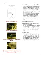
Figure 3-56. Lifting the panels into position, taking
care not to touch the insulation
Figure 3-57. Sealing the seam between the gaskets
Figure 3-58. Tightening the bolts connecting the
panels
The panel bolts should be tightened to a torque
of 90 in-lb (7-1/2 ft-lb).
Do not
ov
er-tighten.
!
DANGER
WARNING
Содержание FLE
Страница 1: ...Model FLE Assembly Instructions 750 192 07 09 Field Erectable Flexible Watertube Boiler ...
Страница 4: ...iv Notes ...
Страница 8: ...viii ...
Страница 16: ...General Description Model FLE Assembly 1 8 750 192 ...
Страница 34: ...3 2 750 192 Figure 3 1 Typical Hot Water Flextube Casing ...
Страница 36: ...3 4 750 192 Figure 3 2 Typical Low Pressure Steam Flextube Casing ...
Страница 38: ...3 6 750 192 Figure 3 3 Typical High Pressure Steam Flextube Casing ...
Страница 56: ...Casing Assembly Model FLE Assembly 3 24 750 192 ...
Страница 58: ...750 192 4 2 Figure 4 2 Fuel Train Components ...
Страница 60: ...4 4 750 192 Figure 4 5 Typical conduit layout ProFire burner on a hot water Flextube boiler ...
Страница 61: ...750 192 4 5 Figure 4 6 Typical conduit layout ProFire burner on a steam Flextube boiler ...
Страница 62: ...4 6 750 192 Figure 4 7 Nameplate locations hot water boiler ...
Страница 63: ...750 192 4 7 Figure 4 8 Nameplate locations steam boiler ...
Страница 64: ...e mail info cleaverbrooks com Web Address http www cleaverbrooks com ...


