


Casing Assembly
Model FLE Assembly
3-16
750-192
9. Install Burner Door
•
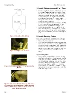
Trim the insulation on the inside of the boiler at
a 45º angle (Figure 3-32).
•
Pack any gaps in the insulation.
•
Using spray adhesive, install the rope gasket on
the front wall inside the bolt pattern. This time,
the gasket should wrap around the opening
twice.
•
Lift the burner door into position and install the
two 3/4" x 4-1/2” cap screws as hinge pins
•
Check the swing and fit of the burner door
against the insulation. The insulation should be
tight around the burner door.
•
The door should be closed gently to keep the
insulation on the front wall. If the door will not
close, pull it open and tap down the insulation
in the area that is preventing the door from clos-
ing.
•
Install washers and brass nuts to evenly pull the
burner door into the opening. Start at the side
farthest from the hinges, moving towards them
as you tighten.
•
Look inside the opening. If any insulation is visi-
ble, it must be packed.
•
Place your hand inside the opening and feel
around the opening. With the heel of your hand,
pack any gaps between the door and the insula-
tion.
Figure 3-32. Cutting Insulation from the Burner
Door
Figure 3-33. Tighten nuts on burner door to hold the
two front wall halves together
Figure 3-31. Cut Pyrobloc from Burner door.
Содержание FLE
Страница 1: ...Model FLE Assembly Instructions 750 192 07 09 Field Erectable Flexible Watertube Boiler ...
Страница 4: ...iv Notes ...
Страница 8: ...viii ...
Страница 16: ...General Description Model FLE Assembly 1 8 750 192 ...
Страница 34: ...3 2 750 192 Figure 3 1 Typical Hot Water Flextube Casing ...
Страница 36: ...3 4 750 192 Figure 3 2 Typical Low Pressure Steam Flextube Casing ...
Страница 38: ...3 6 750 192 Figure 3 3 Typical High Pressure Steam Flextube Casing ...
Страница 56: ...Casing Assembly Model FLE Assembly 3 24 750 192 ...
Страница 58: ...750 192 4 2 Figure 4 2 Fuel Train Components ...
Страница 60: ...4 4 750 192 Figure 4 5 Typical conduit layout ProFire burner on a hot water Flextube boiler ...
Страница 61: ...750 192 4 5 Figure 4 6 Typical conduit layout ProFire burner on a steam Flextube boiler ...
Страница 62: ...4 6 750 192 Figure 4 7 Nameplate locations hot water boiler ...
Страница 63: ...750 192 4 7 Figure 4 8 Nameplate locations steam boiler ...
Страница 64: ...e mail info cleaverbrooks com Web Address http www cleaverbrooks com ...


