


Operation
3-2
750-297
Profire E/LNE Series Manual
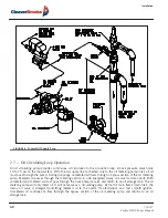
3.1.1 — Oil Flow
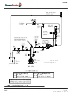
Refer to piping diagrams. Open all valves in the oil suction and return line. The burner oil metering units are not
capable of creating suction. Fuel oil must be supplied to the metering unit at a nominal 10 to 15 psi pressure by a
circulating supply pump.
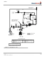
3.1.2 — Oil Pressure
The system pressure is regulated by the back pressure valve. This should be set between 10 to 15 psi at the burner inlet
after the temperature stabilizes.
3.1.3 — Firing Preparations for Oil Burners
Prior to initial firing, oil flow pressure and temperature should be verified.
Inspect the compressor lube oil sump level. Add oil to bring the oil level to the midpoint or slightly higher in the
reservoir sight glass.
Make certain that the drive belts or couplings are aligned and properly adjusted.
To verify air flow and pressure, momentarily flip the switch “ON” and immediately turn “OFF.” The programmer will
continue through its cycle, however, without ignition or energizing the fuel valves. Observe the air pressure gauge.
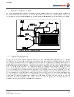
With the compressor running and no oil flow, the pressure should be approximately 10 psi. The schematic flow
diagrams in Chapter 1 indicate the flow of fuel and atomizing air.
If the burner is a dual fuel model, make certain that the main gas shutoff cock is closed and the fuel selector switch is
set to “OIL.”
3.1.4 — Firing Preparations for Gas Burners
A representative of the gas utility should turn on the gas. Determine by a test gauge upstream of the burner regulator
that sufficient pressure exists at the entrance to the gas train. The gas pressure regulator must be adjusted to the pressure
required and the pressure setting recorded.
On combination fuel models, set the selector switch to “GAS.” On initial startup, it is recommended that the main gas
shutoff cock remain closed until the programmer has cycled through pre-purge and pilot sequences to determine that
the main gas valve opens. Turn the burner switch “OFF” and let the programmer finish its cycle. Check to see that the
gas valve closes tightly. Set the high and low gas pressure switches.
Check for leaks and determine there is adequate gas pressure available at the burner for operating at full capacity.
Check with the local utility if necessary. Check gas pressure at the pilot and the main burner. Close the manual gas
valve.
3.2 — Electrical Interference Test
Prior to putting the burner into service, conduct the following test to ascertain that the ignition spark will not cause the
flame relay to pull in.
Содержание Profire E Series
Страница 2: ...E LNE SERIES Installation Operation and Service Manual Manual Number 750 297 Release Date July 2019...
Страница 24: ...Introduction 1 10 750 297 Profire E LNE Series Manual...
Страница 44: ...Operation 3 8 750 297 Profire E LNE Series Manual...
Страница 70: ...Troubleshooting 6 6 750 297 Profire E LNE Series Manual...
Страница 79: ...750 297 Profire E LNE Series Manual 8 5 LNE Series FGR System FIGURE 8 4 Temperature Interlocks...
Страница 82: ...750 297 Profire E LNE Series Manual...