background image

Copyright © 2012 Clayton Associates Inc. 


Electric Powered Vacuum Operational Procedures 

 
Ensure that the electrical supply is properly grounded. If unsure, consult a licensed electrician. Connect vacuum power 
cord to outlet.  
 
Insert a vacuum hose into one of the vacuum ports. One end of each hose has a metal sleeve – insert this end into the 
vacuum port. Connect the end of the airline to one of the three air couplers located between the vacuum ports. This 
connection can be made by pushing the airline plug directly into the coupler. 
Turn the vacuum control switches to the ON positions.  The vacuum will start operation. 
 

 If vacuum is used for sanding or grinding, follow the directions below. 

 
Connect the 1/2” air supply to the vacuum air intake, beneath the power switches. Never allow air pressure to exceed 120 
PSI. 
Connect the vacuum exhaust of the tool to the end of the vacuum hose by threading the cuff onto the hose.  Connect the 
air fitting on the tool to the airline coupler of the adapter hose.  
Choose the proper size of abrasive for the pneumatic tool. If you are unsure of the proper grit abrasive, check with a 
supervisor.   
 
CAUTION: Always use a higher-numbered (finer) grit if unsure.  Lower numbered (rougher) grits can damage the skin of 
some aircraft.   
 
Lay the abrasive onto the backup pad, with the abrasive side facing away from the tool.  Ensure that the abrasive sheet 
covers the backup pad completely, and that the abrasive is oriented properly.  Press the tool against a flat surface with the 
abrasive down, to affix the abrasive to the backup pad. 
 
Place the pneumatic tool on the work surface.  Keep the abrasive flat against the work surface, and depress the throttle 
paddle on the top of the tool.  Keep the tool against the work surface at all times while the tool is in motion.  Operating a 
sander while the abrasive is not touching the work surface can cause the abrasive to spin off of the backup pad.   
 
To control the speed of each tool, locate the speed control valve beneath the tool air intake.  Turn the valve control 
clockwise to reduce the speed of the tool, and counter clockwise to increase the speed. 
 
If two or three technicians will be operating the system at once, follow the same procedure above using the two remaining 
couplers and ports.  The air manifold can support up to three airlines.  Additional airlines should be hooked directly to the 
shop air supply.   

Содержание DUSTMASTER 660-DM-1000

Страница 1: ... Systems Although this manual details maintenance and operation of Clayton pneumatic tools in conjunction with the vacuum these tools are sold separately or as part of a kit Purchasers of the DustMaster vacuum systems may choose to purchase pneumatic tools hoses or accessories from Clayton Associates Inc Clayton Associates Inc www VacuumSanding com 1650 Oak Street Lakewood NJ 08701 www DustlessMad...

Страница 2: ...Copyright 2012 Clayton Associates Inc This page intentionally left blank ...

Страница 3: ...2012 Clayton Associates Inc Table of Contents Introduction 1 Warnings Cautions 2 Preparations 3 DM 100 300 Operations 4 DM 104 304 Operations 5 Filter Change 6 Vacuum Maintenance 16 Troubleshooting 17 Warranty 19 ...

Страница 4: ...ad this manual thoroughly and understand proper use and maintenance of the system The procedures herein provide a method for performing dust and debris collection while minimizing the particulate contamination of hazardous dust into the air ground and water Failure to follow proper operational procedures and Safe Filter Change instructions can result in personal exposure damage to equipment or per...

Страница 5: ... dry or damp not wet matter Free flowing liquids may damage the ULPA filter and will void the warranty Always store equipment in dry area All vacuums must be grounded during operation Use a conductive air supply hose or attach a grounding wire to pneumatic vacuums Always connect electric vacuums to a properly grounded outlet Failure to use a properly grounded outlet could result in electrocution i...

Страница 6: ...ize airline will supply enough compressed air to power the vacuum and up to three pneumatic tools The vacuum can operate from a airline if no pneumatic tools are connected Pneumatic vacuums are shipped with a compressed air filter in a separate box Thread the compressed air filter into the air inlet on the vacuum Failure to install filter may cause premature motor failure Preparation for Storage T...

Страница 7: ...oper grit abrasive check with a supervisor CAUTION Always use a higher numbered finer grit if unsure Lower numbered rougher grits can damage the skin of some aircraft Lay the abrasive onto the backup pad with the abrasive side facing away from the tool Ensure that the abrasive sheet covers the backup pad completely and that the abrasive is oriented properly Press the tool against a flat surface wi...

Страница 8: ...line plug directly into the coupler Turn the vacuum control switches to the ON or AUTO position The vacuum will now be operational If vacuum is used for sanding or grinding follow the directions below Connect the 1 2 air supply to the vacuum air intake beneath the power switches Never allow air pressure to exceed 120 PSI Connect the vacuum exhaust of the tool to the end of the vacuum hose by threa...

Страница 9: ...ols to remove traces of Hexavalent Chromium and heavy metals Hexoff is manufactured under license from the Center for Disease Control and has been proven to remove hexavalent chromium at the microscopic level PN 415 SC01Q Hexoff Surface Decontamination spray 1 QT bottle PN 415 NR045 Hexoff No Rinse Wipes 45 count canister PN 415 NR800 Hexoff No Rinse Wipes 800 count tub Safe Filter Change Procedur...

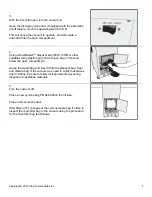
Страница 10: ...sturdy plastic bag hold the open bag in front and below the open compartment Grasp the waste bag and insert it into the disposal bag Seal and discard bag If the vacuum was used to collect hazardous dust or debris be sure to follow all requirements governing disposal of hazardous materials 5 Turn the vacuum off Place a new cyclone bag PN 926 050on the fill tube Close and secure the door After fifte...

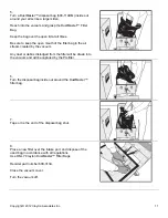
Страница 11: ...to remove the bag from the compartment On models equipped with a cyclone separator this interior filter bag should be checked after the cyclone bag has been changed fifteen 15 times DM 300 304 vacuums have a cyclone separator section that must be disconnected in order to access the vacuum filter compartment 1 Turn the vacuum on Briefly flip open each of the 3 inlet ports to clear any dust that mig...

Страница 12: ...to the hose tool cabinet 5 While moving the separator section use one hand to guide the three 3 compressed air hoses so that they do not hang up on the separator cabinet while moving it 6 Allow the cyclone section to move away from the hose tool cabinet until the top lies on the floor From this point onward follow the instructions for all DM Series Vacuums ...

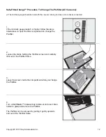
Страница 13: ...Use your thumb to release the safety clip on the latch and then lift the handle to release the latch 3 Unlatch the vacuum cover and open the lid 1 2 Turn on the vacuum and then open the lid completely 4 Push gently on the filter bag with a stick or tool to check the quantity of dust in the bag If the bag is to full perform the filter change Do not wait for the bag to be full a full filter bag can ...

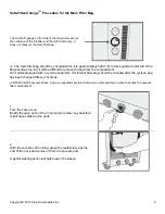
Страница 14: ...in the air stream created by the vacuum Any dust or debris dislodged from the filter will be drawn into the vacuum and will be captured by the Prefilter 6 Turn the disposal bag inside out around the DustMaster filter bag 7 Tape or tie the end of the disposal bag shut 8 Place a new filter over the intake port and dispose of the used bag in accordance with all regulations Use ONLY Clayton DustMaster...

Страница 15: ...llow the steps listed above to open the filter compartment to change the Prefilter 2 Loosen the knobs holding the Prefilter screen and carefully lift it out of the Prefilter frame 3 Leave the screen inside the compartment while you change the Prefilter 4 Turn a DustMaster disposal bag inside out and use it like a mitten to grasp and remove the Prefilter The Prefilter can be removed by pulling it g...

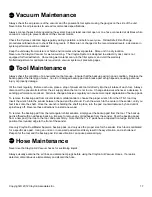
Страница 16: ... Use ONLY Clayton DustMaster Prefilters Part Number 600 115 Shut the lid and latch it securely Turn the vacuum control to the OFF position to shut down the vacuum The minihelic gauge should be read with the vacuum running and one or more hoses connected Change the ULPA filter if the gauge still indicates 5 or higher with a new Prefilter installed Contact Clayton for technical support before attemp...

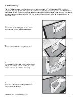
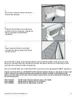
Страница 17: ... dust collected in the vacuum If available we recommend changing the ULPA filter in a controlled environment such as a sanding booth or downdraft room 1 Loosen the knobs holding the prefilter screen and carefully lift it out of the prefilter frame 2 Remove the prefilter by sliding it straight up 3 The prefilter holder is held in place by two metal straps Use a 5 32 Allen key to loosen the set scre...

Страница 18: ...all the prefilter and ensure that there is a filter bag on each inlet tube before closing the filter compartment Be sure to discard filters and contaminated PPE in accordance with appropriate HAZMAT regulations Clayton recommends the use of HEXOFF Surface Decontamination Cleaner to wipe down vacuums and tools to remove traces of Hexavalent Chromium and heavy metals Hexoff is manufactured under lic...

Страница 19: ...tes Inc 16 Filters 926 050 Cyclone Clear Collection Bag 10 pack 610 313A Cyclone Collection Bag Cloth 10 pack 600 313A Filter Bag 5 pack 600 115 Pre Filter 3 pack 600 116 HEPA ULPA Filter 1 pack 600 114DM Waste Disposal Bag 25 pack ...

Страница 20: ... air intake of each tool Always disconnect the pneumatic tool from the air supply when the tool is not in use Change abrasives whenever a decrease in sanding performance is noticed Failure to change abrasives regularly can cause more rapid degradation of backup pads To remove the backup pad from circular random orbital sanders choose the proper wrench from the CTK 1 tool tray Insert the wrench int...

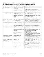
Страница 21: ...k the pressure on facility compressed air system and lower if over 110 PSI Air tools operating too slowly Tool throttle is set too low Pneumatic tool system pressure is too low Not enough volume of air available Increase tool throttle with adjustment knob on tool Increase pressure of supply air to system DO NOT EXCEED TOOL PRESSURE SPECIFICATIONS Confirm that the compressed air supply line is larg...

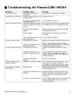
Страница 22: ...ed air supply by installing a properly sized regulator between the compressed air supply and the vacuum system Air tools operating too slowly Tool throttle is set too low Compressed air supply is not adequate in pressure or volume Pneumatic system filter is clogged Increase tool throttle with adjustment knob on tool Increase supplied compressed air pressure or increase the size of the airline feed...

Страница 23: ... will provide parts to the customer s site at no charge and will perform labor at no charge for products returned to its factory at the customer s expense Outside the continental U S Clayton will provide parts to the customer s site at no charge or for products returned to its factory at the customer s expense Clayton will provide parts and perform labor at no charge Clayton shall not in any event...

Страница 24: ...5 2 69 2012 specifically Annex AA Requirements for vacuum cleaners and dust extractors for the collection of hazardous dusts The legally authorized entity established in the EU for compiling the technical file is ExVeritas Limited Unit 16 18 Abenbury Way Wrexham Industrial Estate Wrexham LL13 9UZ United Kingdom File Number 18FILE0423 Subject to use for the purpose for which it was designed in acco...

Страница 25: ...Copyright 2012 Clayton Associates Inc 22 Clayton products are proudly made in the USA ...

Отзывы: