


5. Noise Test
1) connect balanced outputs to a power amplifier. Select
line. Turn the volume up and down manually and
listen for the noise and hum with speaker. Do the
same thing in balance, Tape1 and 2
2) repeat step 1 with single ended outputs
3) repeat steps 1 and 2 with remote control
6. Paper Works
1) turn volume up to 15. measure and record the
offset voltages.
2) Measure and record bias voltages
3) Measure and record the difference in right and left
channels. (in dB)
4) Measure and record the gain (in dB)
7. Audio- Precision Test
1) set-up unit to the computer. Volume must be 30
2) load frequency response test and sweep
3) load THD plus N- Freq. Response test
4) and B must be 0.003%
5) measure noise in dB
8. 1) check the RS232 port
2) reset the unit
3) mark F.T.
Содержание CP-65
Страница 1: ...CP 65 Class PREAMPLIFIER SERVICE MANUAL v 1 0...
Страница 2: ...Index Mechanical Assembly 3 PC Boards 17 Testing Procedures 30 Diagrams 33...
Страница 3: ...CP 65 MECHANICAL ASSEMBLY...
Страница 5: ...FACE PLATE ASSEMBLY 1 2 3 4 5 L214XR01 S 6 Class 2 1 2 3 6 5 4 TOP VIEW SIDE VIEW 1 SIDE VIEW 2 CP 65...
Страница 6: ...CHASSIS REAR VIEW 1 2 3 4 5 6 7 8 Class 3 CP 65...
Страница 7: ...CHASSIS 1 PLA CAPFR1 2 HDW 8 FLAT WASHER 3 BZO 8 32x3 4 BHCS 4 Class 6 1 2 3 4 TOP VIEW CP 65...
Страница 9: ...CP 65 PC BOARDS...
Страница 10: ...MAINBOARD Class 10 CP 65 N A...
Страница 11: ...CP 65 TESTING PROCEDURES...
Страница 12: ...Class 14 START UP CP 65 N A...
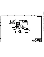
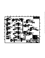
Страница 13: ...CP 65 DIAGRAMS...
Страница 14: ...B2BXR00 Class 16 CP 65...
Страница 15: ...CP65_block sch 1 Thu Jun 20 11 11 21 2002...
Страница 16: ...B2B7XR03_amp sch 1 Thu Jun 20 11 00 56 2002...
Страница 17: ...B2B7XR03_amp sch 2 Thu Jun 20 11 01 28 2002...
Страница 18: ...B2B6XR00_IR_input sch 1 Thu Jun 20 10 59 40 2002...
Страница 19: ...B2B5XR01_Encoder sch 1 Thu Jun 20 10 59 01 2002...
Страница 20: ...B2B4XR01_display_5_button sch 2 Thu Jun 20 11 07 05 2002...
Страница 21: ...B2B4XR01_display_5_button sch 1 Thu Jun 20 11 08 57 2002...
Страница 22: ...B2b2XR00_line input2 sch 1 Thu Jun 20 10 56 01 2002...
Страница 23: ...B2B1XR02_mother_PCB_with cs3310 sch 1 Thu Jun 20 10 51 01 2002...
Страница 24: ...B2B1XR02_mother_PCB_with cs3310 sch 2 Thu Jun 20 10 51 38 2002...
Страница 25: ...B2B1XR02_mother_PCB_with cs3310 sch 3 Thu Jun 20 10 53 20 2002...
Страница 26: ...B2B1XR02_mother_PCB_with cs3310 sch 4 Thu Jun 20 10 54 28 2002...
Страница 27: ...B2B1XR02_mother_PCB_with cs3310 sch 5 Thu Jun 20 10 55 06 2002...
Страница 28: ...B2B8XR02_ext ps sch 1 Thu Jun 20 11 13 08 2002...
Страница 36: ......


