background image

Clarke

®


 American Sanders

  Super  E  Operator's  Manual

       Page 9

ADJUSTMENT PROCEDURES  (cont)

Condition - Pad creates a ridge on only one side of the
pad: Either rotate the stem of the side effected clock-
wise or rotate the stem opposite conterclockwise,
depending on whether the ridge terminates beyond the
tip of the pad or prior to it.  If it is prior to the tip, adjust
the side effected, otherwise adjust the opposite side.

Belt Tension

The design of the belt allows it to deliver the power with
very little tenstion.  The tension should be great
enough to prevent slippage and wear.  Excessive
tension will only shorten bearing and belt life.

ROUTINE MAINTENANCE

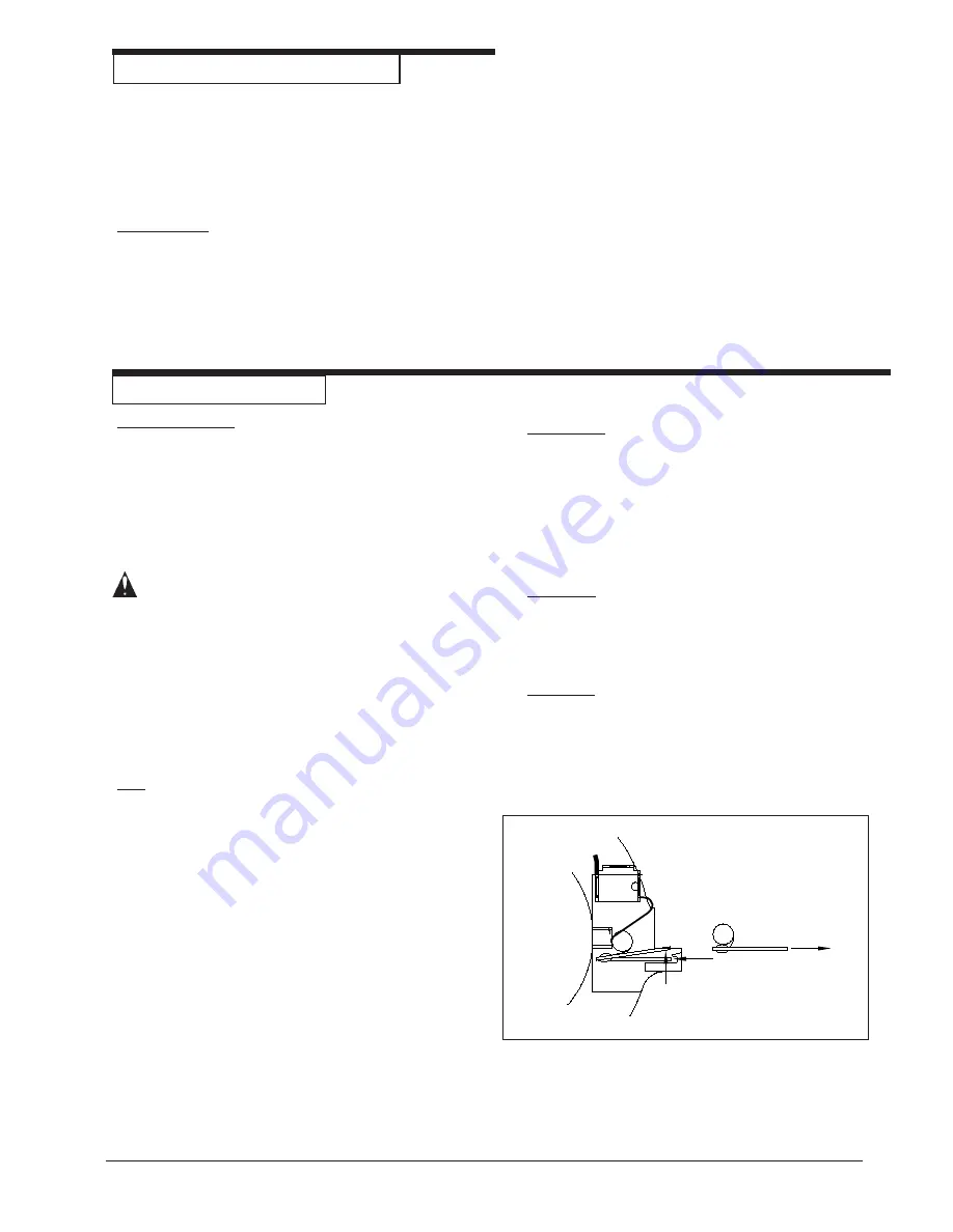
Carbon Brushes

Inspect all four brushes every 6 months or 250 hours.
Access to the brushes is gained through the front and
back motor vent plugs and under both covers.  Press
tab on spring clip assembly in, rotate, then remove
(figure 5).  Use needlenose pliers to disconnect the
shunt wire.  If any brush has worn to 3/8" in length or
shorter, replace the entire set.

CAUTION: Use only motor brush part no. 40818A

or 40055A with shunt wire or motor
failure will occur.

When replacing the brushes, make sure that the brush
seats against the commutator, the tab on the spring
clip assembly is fully seated in pocket, and the brush
is free to travel.  When returning the switch covers,
keep all wires clear of the commutator and any pinch
sites.

Pad

In time the elastomer on the pad may wear or become
damaged.  To replace, remove pad by placing screw-
driver in slot of shaft, grasp pad and rotate shaft
counterclockwise.  Remove existing elastomer and
clean hub throughly to remove old adhesive.  Roughen
surface of new elastomer to provide good bond sights.
Apply a good rubber cement to both surfaces and allow
to tack.  3M# 1300 rubber and gasket cement is a
suitable choice.  Apply elastomer to hub and knead
throughly.  Apply pressure to elastomer and allow to
stand over night.  Apply a medium strength thread
locker to the external threaded end of the shaft.  Install
belt in grooves  on hub and screw down on shaft.
Install abrasive retainer on to shaft.  Locate a flat
surface and tape 80 grit abrasive to surface.  Using
machine "dress in" by sanding the elastomer on the
pad.  Continue sanding until the entire surface of the
elastomer shows signs of sanding.  As in operation of
the machine, take precautions performing this proce-
dure.

Pad Driver

Periodically inspect belt grooves on pad driver for an
accumulation of paint or varnish especially after jobs
where several layers of paint or varnish have been
removed.  Particles of paint or varnish can deposit in
the grooves, creating vibration and damaging the
drive belt.  Use a plastic putty knife or similar object to
remove the deposits.

Dust Bag

Periodically the dust bag should be turned inside out,
shaken vigorously and machine washed in cold water
to prevent pore blockage and loss of dust control.

Bearings

To insure reliable performance, armature and pad
driver bearings should be inspected for wear or
damage after 1500 hours.  If used heavily the bear-
ings should be replaced seasonally.

Figure 5

Содержание Super E Edger

Страница 1: ...roperty could occur as well You must have training in the operation of this machine beforeusingit Ifyouoryouroperator s cannotreadEnglish havethismanualexplainedfullybefore attempting to operate this...

Страница 2: ...ing Cuts and Sandpaper 6 MachineSet Up 7 Operating Instructions 8 Adjustment Procedures 8 Leveling 8 Belt Tension 9 RoutineMaintenance 9 CarbonBrushes 9 Bearings 9 Pad 9 Pad Driver 9 AssemblyDrawing 1...

Страница 3: ...adhered to Cigarette lighters pilot lights and any other source of ignition can create an explosion when active during a sanding session All sources of ignition should be extinguished or removed entir...

Страница 4: ...ons are fastened to the machine Get new labels from your authorized Clarke American Sanders distributor WARNING Sanding dust can be airborne and can be breathed in while operating a sander Always wear...

Страница 5: ...706A Extension13 5 inch 13inches 3200RPM 13708A ExtensionPicket 3 inch 47 8 inches 5900RPM 10019C ExtensionPicket 3 inch 47 8 inches 5900RPM w turn Specifications Model 07068C Super E 115V 07074C Supe...

Страница 6: ...on the floor surface A coarse abrasive should be used If glazing loading or burning takes place immediately into an initial cut select a coarser abrasive If this should occur during an initial cut th...

Страница 7: ...heir respective grooves on the pad driver and motor pulley 4 Install belt guard 5 Remove screw and abrasive retainer Center abrasive on pad and secure with abrasive retainer and screw Figure 2 2 b 6 R...

Страница 8: ...upply cable from machine whenever servicing replacing abrasive or emptying the dust bag could result in electrocution or severe injury Never leave machine unattended while the supply cable is connecte...

Страница 9: ...ed To replace remove pad by placing screw driver in slot of shaft grasp pad and rotate shaft counterclockwise Remove existing elastomer and clean hub throughly to remove old adhesive Roughen surface o...

Страница 10: ...ders Super E Operator s Manual Model Super E Edger Drawing 1 1 03 1 2 3 4 5 6 7 8 9 10 11 12 13 14 50 25 15 18 57 21 19 20 22 24 26 59 27 28 29 30 31 32 33 34 35 36 58 37 38 39 40 41 42 36 43 44 45 46...

Страница 11: ...89 Screw 20 x Sc Hd 4 27 21109A Bracket Exhaust 1 28 293406 Gasket Exhaust 1 29 920196 Nut 13 Jam 2 30 52132A Assembly Caster 2 31 66199A Pulley Motor 1 32 980646 Washer 1 33 81302A Nut 20 Jam 1 34 91...

Страница 12: ...American Sanders Super E Operator s Manual Model Super E Edger Drawing 2 1 03 12 13 14 19 15 16 18 24 30 5 6 29 28 4 27 26 17 1 2 3 4 5 6 7 8 4 9 10 11 31 15 32 33 17 26 4 24 5 8 7 6 20 21 24 5 6 22...

Страница 13: ...2 25 58324A Shaft 1 67471A Shaft 3 Turn 1 26 57396A RetainerBearing 1 27 34109A Guard Disc 1 28 66973A RetainerDiscGuard 1 29 62722A Driver Pad 7 1 30 962727 Screw 8 32 x 3 31 22902A Extension Kick T...

Страница 14: ...Page 14 Clarke American Sanders Super E Operator s Manual Model Super E Edger Wiring Diagram 1 96...

Страница 15: ...nogatan 18 Box 4029 S 431 04 Molndal 46 31 706 73 00 ALTO Norge A S Oslo Norway Bjornerudveien 24 N 1266 47 2275 1770 U S A Locations European Locations HEAD OFFICE ALTO U S Inc St Louis Missouri 1625...

Страница 16: ...repair location Transportation charges to and from the repair location must be prepaid by the purchaser c Clarke American Sanders will repair the product and or replace any defective parts without cha...

Отзывы: