21
(i) WELDING CURRENT CONTROL
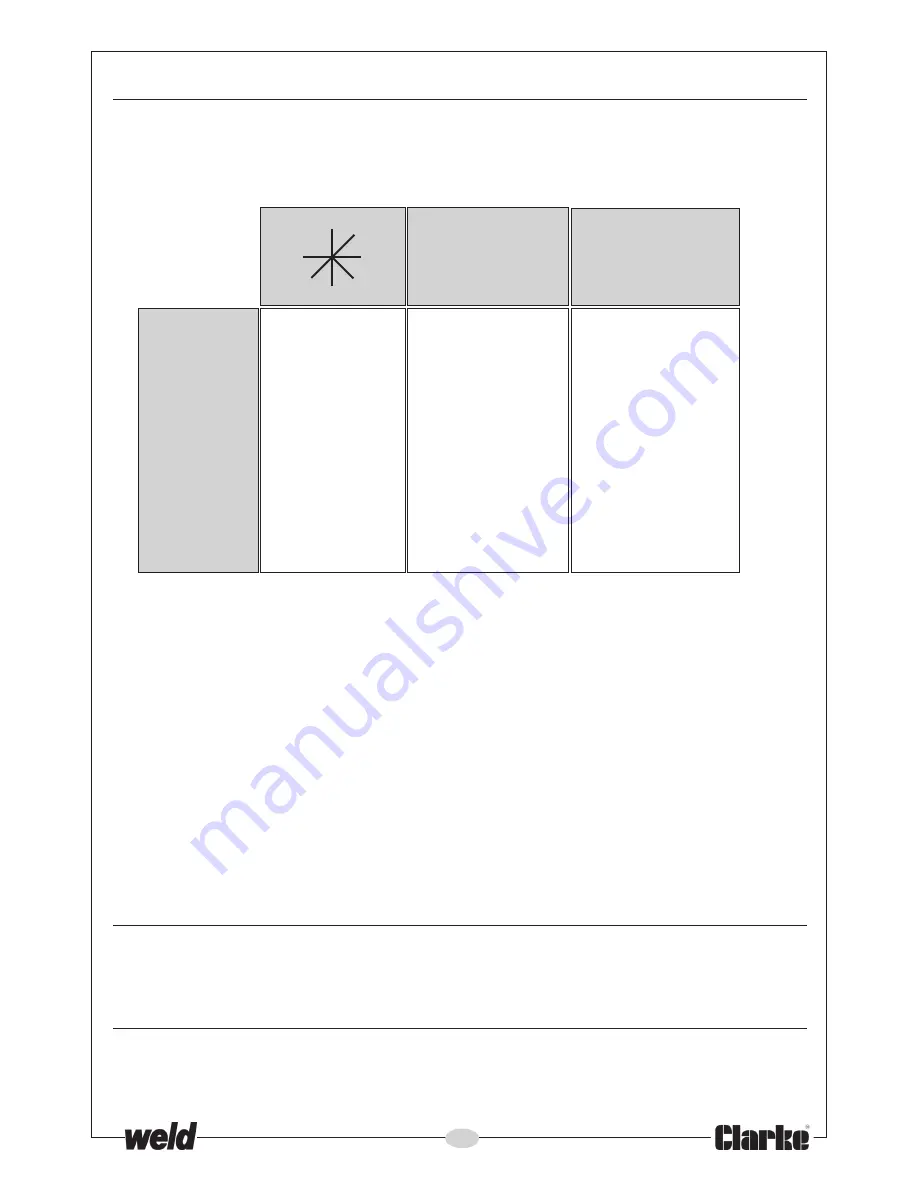
Select the welding current according to the type of metal and thickness to be welded. The control
has 7 positions as indicated in the chart below. Experience will determine the optimum setting for
the job in hand, but the chart gives general settings from which to work.
PLEASE NOTE: If the current and hence the wire speed is increased, the volume of
gas at the nozzle must also be increased. Turn the regulator knob accordingly.
(ii) WIRE FEED SPEED CONTROL
The WIRE FEED Rotary Control Knob, with graduations from 0 to 10, is used to fine tune the
wire speed feed to the nozzle. The knob should be set to position 6 to begin with for welding
steel, and 8 for welding aluminium, then adjusted as required.
Note: This control is for fine tuning the wire speed. The speed of wire delivery will
increase automatically as the current is increased and vice versa. Therefore,
once the ideal speed is achieved by fine tuning, it should not be necessary to
adjust this control when the welding current is changed.
It is always better to start with too high a speed, and back off slightly, to avoid
the possibility of the wire welding itself to the tip.
Timer Control
This is explained in more detail
on page 23. Fo
r all normal welding operations, set this control to
zero.
Welding Wire
Trim the welding wire so that it protrudes no more than 5mm from the end of the shroud.
1
0.6
LOW
2
0.6
LOW
3
0.6 - 0.8
MEDIUM
4
0.6 - 0.8
MEDIUM
5
0.8
MEDIUM _ HIGH
6
0.8
HIGH
7
1.0
HIGH
Steel Wire
Diameter
(mm)
Wire Speed
Adjustment
Switch
Positions
3
4
5
1
2
6
7
Содержание MIG220TE
Страница 1: ...OPERATING MAINTENANCE INSTRUCTIONS 11 16 MIG220TE MIG255TEC MIG270TE WELDERS...
Страница 14: ...14 GENERAL LAYOUT Fig 2...
Страница 27: ...27 WIRING DIAGRAM MIG220TE...
Страница 28: ...28 WIRING DIAGRAM MIG255TEC...
Страница 29: ...29 WIRING DIAGRAM MIG270TE...
Страница 30: ...30 PARTS DIAGRAM MIG220TE...
Страница 32: ...32 PARTS DIAGRAM MIG255TEC...
Страница 34: ...34 PARTS DIAGRAM MIG270TE...
Страница 36: ......


