Fig. 20
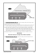
Female joint - laminate face down.
7.
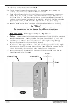
Male Joint (Fig. 21)
-
Place the worktop with the laminate face up.
8.
Fully insert two pins in the jig holes marked
‘M’
with angle symbol
.
9.
Refer to page 10, (cutting to length) to determine where to mark the pencil line for
positioning the jig on the worktop.
10.
Ensure the 2 pins in holes marked
‘M’
are pushed firmly against the post form edge
and the jig on the pencil line (
Fig. 17
).
Fig. 21
11.
Firmly clamp the jig to the worktop ensuring it doesn’t move as you do so. Ensure the
clamps do not obstruct the router path.
12.
Cutting
- Follow steps
6 - 9
on page 6.
-15-
Pencil Line
Male Joint - Laminate face up.
Cut Direction
Cut Direction
Post Form Edge
Post Form Edge
Содержание CONTRACTOR 6462118
Страница 20: ......


