Fig. 15
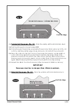
Female joint - laminate face up.
4.
Ensure the 2 pins in holes
‘F’
are pushed firmly against the post form edge of the
worktop, clamp the jig to the worktop ensuring clamps do not obstruct the router
path.
5.
Once the cut is complete, remove the excess (
Fig. 16
hatched area), using either
the router or a fine tooth saw.
6.
Cutting
- Follow steps
6 - 9
on page 6.
700mm
-12-
7.
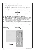
Male Joint (Fig. 17)
-
Place the worktop with the laminate face down, taking
care to protect the surface.
8.
Fully insert two pins in the jig holes marked
‘M’
with angle symbol
.
9.
Refer to page 10, (cutting to length) to determine where to mark the pencil line for
positioning the jig on the worktop.
10.
Ensure the 2 pins in holes marked
‘M’
are pushed firmly against the post form edge
and the jig on the pencil line (
Fig. 17
).
Fig. 16
Cut Direction
Post Form Edge
Содержание CONTRACTOR 6462118
Страница 20: ......


