26
❑
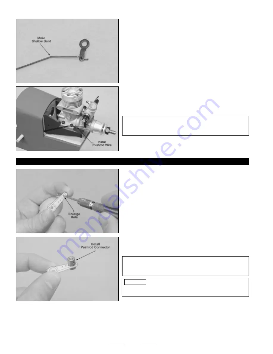
Using a pair of pliers, make a shallow bend in the pushrod wire, 1"
behind the Z-Bend. This will allow the pushrod wire to line up with the
throttle arm when it's installed.
❑
Slide the plain end of the throttle pushrod wire into the plastic guide
tube in the firewall, then reinstall the throttle arm onto your engine.
✦
✦
✦
✦
✦
IMPORTANT
✦
✦
✦
✦
✦
So that the pushrod wire doesn't bind, you may
need to adjust the bend in the pushrod wire so that it lines up better
with your engine's throttle arm.
STEP 3: INSTALLING THE ADJUSTABLE PUSHROD CONNECTOR
❑
Using a modeling knife, cut away all but one arm from a "4-point"
servo horn.
❑
Enlarge the hole in the servo arm that is 11/16" out from the center of
the servo arm, using a 5/64" diameter drill bit.
❑
Install the adjustable pushrod connector into the enlarged hole in
the servo arm.
✦
✦
✦
✦
✦
IMPORTANT
✦
✦
✦
✦
✦
When threading on the knurled nut, don't tighten
the nut completely. You don't want the pushrod connector loose, but
you do want it to be able to rotate without binding.
To prevent the knurled nut from loosening during flight,
apply a drop of thin C/A to it. Allow the C/A to fully cure before
proceeding.
Continued On Next Page
☛
☛
☛
☛
☛
PRO TIP
❑
Connect your radio system and plug the throttle servo into the receiver. Check to ensure that the throttle servo output shaft
is rotating in the correct direction. When the throttle control stick is moved forward, from the idle to the full throttle position, the
servo output shaft should rotate in the correct direction to open your engine's carburetor. If it doesn't, flip the servo reversing
switch on your transmitter.
☞
For the Magnum XL .28A, the servo output shaft should rotate counterclockwise to open the carburetor.


