


Reassembly
1. Reassembly is the reverse of the disassembly procedure. If a new
disc has been installed, it may require a different number of spacer
washers to obtain the right amount of "grip" on the disc. When the di-
aphragm assembly has been tightened to a point where the di-
aphragm cannot be twisted, the disc should be compressed very
slightly by the disc guide. Excessive compression should be avoided.
Use just enough spacer washers to hold it firmly.
2. Make sure the stem nut is made up very tight. Attach a good fit-
ting wrench to the nut and give it a sharp "rap" rather than a steady
pull. Usually several blows are sufficient to tighten the nut for final
tightening. Failure to do so could allow the diaphragm to pull loose
and tear when subjected to pressure.
3. Carefully install the diaphragm assembly by lowering the stem
through the seat bearing. Take care not to damage the stem or bear-
ing. Line up the diaphragm holes with the stud or bolt holes on the
body. On larger valves with studs, it may be necessary
to hold the diaphragm assembly up while stretching the di-
aphragm over the studs.
4. Put spring in place and replace cover. Maker sure diaphragm
is laying smooth under cover.
5. Tighten cover nuts firmly using a cross-over pattern until all nuts
are tight.
Test Procedure After Valve Assembly
1. Check the diaphragm assembly for freedom of movement by
inserting a rod into the threaded hole in the top of the valve
stem and lifting the diaphragm assembly manually. The di-
aphragm assembly should move freely without any signs of
sticking or grabbing. (See "Freedom of Movement Check" sec-
tion.
2. Re-install the pilot system and tubing exactly as it was prior to
removal.
3. Follow steps under "Start-Up and Adjustment" Section in N-
90-21 UL Sheet.
When block and tackle or a power hoist is to be used to lift valve
cover, insert proper size eye bolt in place of the center cover plug.
On 8” valves only, there are 4 holds 3/8" - 11 size where jacking
screws maybe inserted to break cover loose from the body and then
4 eye bolts may be inserted for lifting purposes.
Pull cover straight
up
to keep from damaging the integral seat bearing and stem.
4
. Remove the diaphragm and disc assembly from the valve body.
With smaller valves this can be accomplished by hand,
pulling
straight up on the stem so as not to damage the seat bearing.
On large valves, an eye bolt of proper size can be installed in the
stem and the diaphragm assembly can be then lifted with a block
and tackle or power hoist. Take care not to damage the stem or bear-
ings. The valve won't work if these are damaged.
5.
The next item to remove is the stem nut. Examine the stem
threads above the nut for signs of mineral deposits or corrosion. If
the threads are not clean, use a wire brush to remove as much of the
residue as possible. Attach a good fitting wrench to the nut and give
it a sharp “rap” rather than a steady pull. Usually several blows are
sufficient to loosen the nut for further removal. On the smaller valves,
the entire diaphragm assembly can be held by the stem in a vise
equipped with soft brass jaws
before removing the stem nut.
The use of a pipe wrench or a vise without soft brass jaws scars the
fine finish on the stem. No amount of careful dressing can restore the
stem to its original condition. Damage to the finish of the stem can
cause the stem to bind in the bearings and the valve will not open or
close.
6
. After the stem nut has been removed, the diaphragm assembly
breaks down into its component parts. Removal of the disc from the
disc retainer can be a problem if the valve has been in service for a
long time. Using two screwdrivers inserted along the outside edge
of the disc usually will accomplish its removal. Care should be taken
to preserve the spacer washers in water, particularly if no new ones
are available for re-assembly.
7.
The only part left in the valve body is the seat which ordinarily
does not require removal. Careful cleaning and polishing of inside
and outside surfaces with 400 wet/dry sandpaper will usually re-
store the seat’s sharp edge. If, however, it is badly worn and re-
placement is necessary, it can be easily removed.
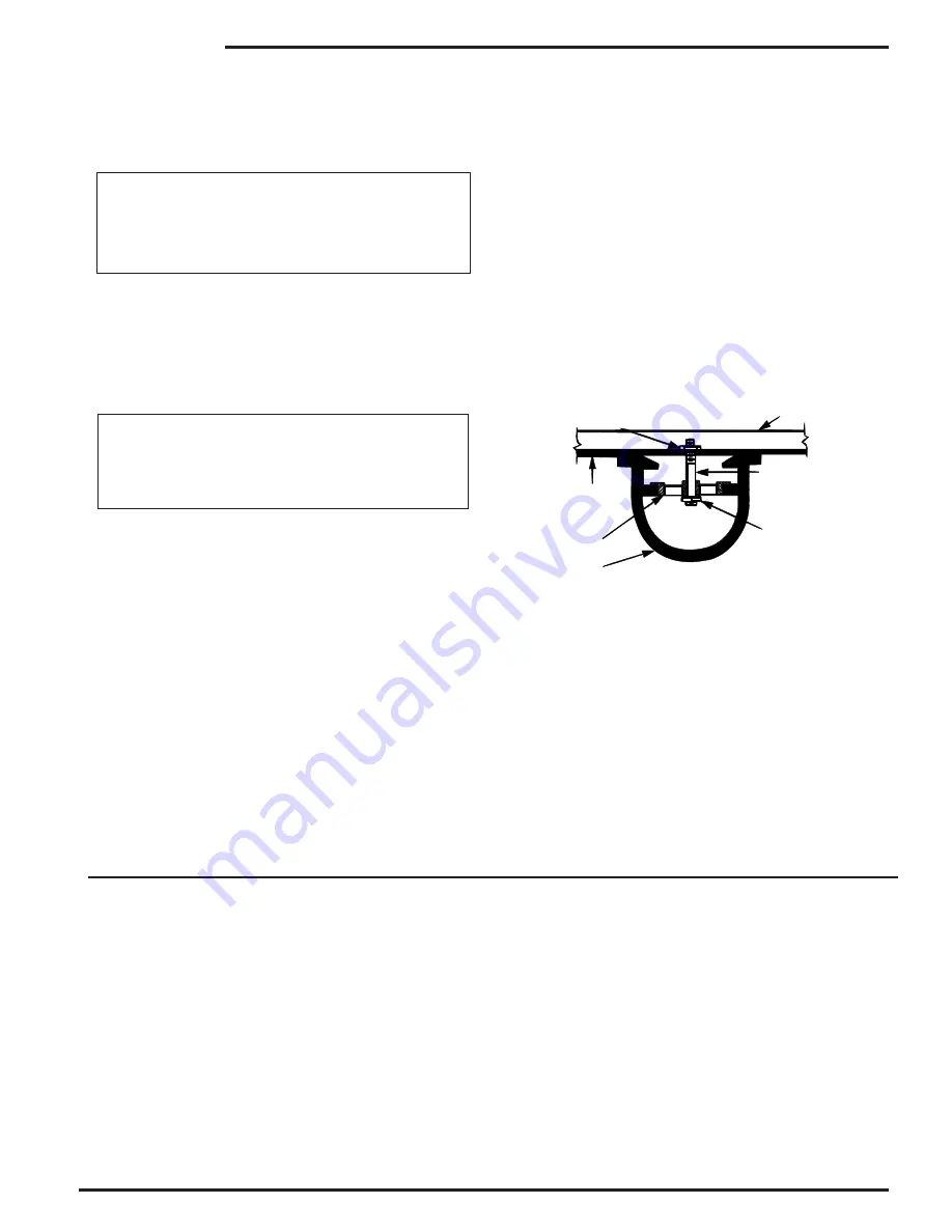
Seats in valve sizes 1 1/4” through 6” are threaded into the valve
body. They can be removed with accessory X109 Seat Removing
Tool available from the factory. On 8” and larger valves, the seat is
held in place by flat head machine screws. Use a tight-fitting, long
shank screwdriver to prevent damage to seat screws. If upon re-
moval of the screws the seat cannot be lifted out, it will be neces-
sary to use a piece of angle or channel iron with a hole drilled in the
center. Place it across the body so a long stud can be inserted
through the center hole in the seat and the hole in the angle iron.
By tightening the nut a uniform upward force is exerted on the seat
for removal.
NOTE
: Do not lift up on the end of the angle iron as this may force
the integral bearing out of alignment, causing the stem to bind.
Lime Deposits
One of the easiest ways to remove lime deposits from the valve
stem is to dip it in a 5-percent muriatic acid solution just long
enough for the deposit to dissolve. This will remove most of the
common types of deposits.
CAUTION: USE EXTREME CARE
WHEN HANDLING ACID, RINSE PARTS IN WATER BEFORE
HANDLING.
If the deposit is not removed by acid, the a fine grit
(400) wet or dry paper can be used with water.
Inspection of Parts
After the valve has been disassembled, each part should be ex-
amined carefully for signs of wear, corrosion, or any other abnor-
mal conditions. Usually, it is a good idea to replace the rubber
parts (diaphragm and disc) unless they are free of signs of wear.
Any other parts which appear doubtful should be replaced.
100-01 UL
VALVE STEM THREAD SIZE
Valve Size
Thread Size (UNF Internal)
1 1/4"—2 1/2"
10—32
3"—4"
1/4—28
6"—8"
3/8—24
COVER CENTER PLUG SIZE
Valve Size
Thread Size (NPT)
1 1/4"—1 1/2"
1/4"
2"—3"
1/2"
4"—6"
3/4"
8"
1"
NUT
ANGLE OR CHANNEL IRON
LONG STUD OR BOLT
NUT OR BOLT HEAD
DO NOT
LIFT
VALVE SEAT
VALVE BODY
Distributed By: M&M Control Service, Inc.
www.mmcontrol.com/claval-index.php 800-876-0036 847-356-0566
Содержание 90-21
Страница 4: ...Distributed By M M Control Service Inc...
Страница 5: ...Distributed By M M Control Service Inc www mmcontrol com claval index php 800 876 0036 847 356 0566...
Страница 16: ...Distributed By M M Control Service Inc...
Страница 21: ...Distributed By M M Control Service Inc www mmcontrol com claval index php 800 876 0036 847 356 0566...
Страница 22: ...Distributed By M M Control Service Inc www mmcontrol com claval index php 800 876 0036 847 356 0566...
Страница 23: ...Distributed By M M Control Service Inc www mmcontrol com claval index php 800 876 0036 847 356 0566...


