


14
Design & Selection
Caution
If sufficient rigidity cannot be attained, machine
resonance is suppressed to some degree by installing
dummy inertia as close to the actuator as possible.
Examples of adding dummy inertia are shown below.
As a reference, dummy inertia is [load inertia] x
(0.2 to 1). [Fig. 3]
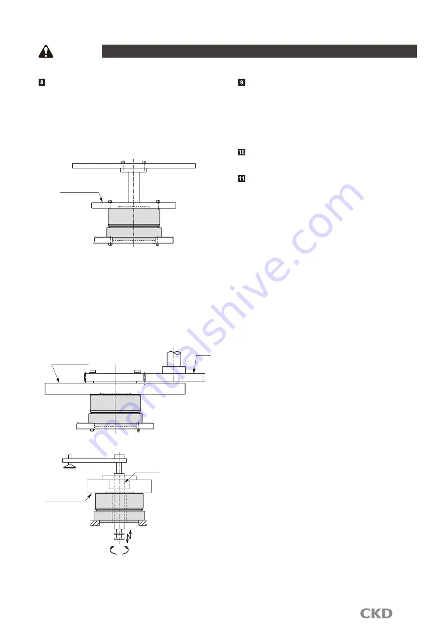
[Fig. 3] Dummy inertia attachment example 1
Dummy inertia
When coupling with a belt, gears, or spline, or when
joining with a key, dummy inertia should be [load
inertia] x (0.5 to 2).
If speed changes with belts or gears, use load inertia
as the actuator output shaft conversion value, and
install dummy inertia on the actuator. [Fig. 4] [Fig. 5]
(CAUTION) Install dummy inertia as large as possible
within the actuator's capacity. (Use steel
that has a large specific gravity.)
[Fig. 4] Dummy inertia attachment example 2
Dummy inertia
Gear
[Fig. 5] Dummy inertia attachment example 3
Dummy inertia
Ball spline
( )
Select gears with as larger
diameters as possible.
The ABSODEX has a built-in absolute resolver
(magnetic position detector).
Do not place strong magnetic fields such as rare earth
magnets near the actuator.
Do not pass high-current wiring through the hollow hole.
If you do, the full performance may not be achieved,
and malfunction or fault may result.
Do not place strong magnetic fields such as rare earth
magnets near the actuator.
For additional notes, please refer to the instruction manual.


