background image

Shutting Down an Interface

PA-T3 Serial Port Adapter Installation and Configuration

8-8

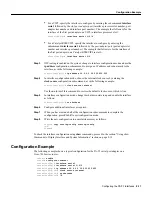
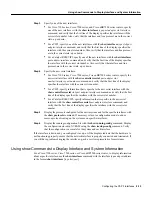
Step 4

Enter the shutdown command as follows:

Router(config-if)# shutdown

Step 5

To shut down additional interfaces, enter the slot/port address (or slot/port
address/interface port for a VIP2) of each additional interface followed by the shutdown
command. When you have entered all the interfaces to be shut down, press Ctrl-Z (hold
down the Control key while you press Z) or enter end to exit configuration mode and
return to the EXEC command interpreter prompt.

The example that follows is for the Cisco 7100 series, Cisco 7200 series, or
Cisco uBR7200 series routers:

Router(config-if)# interface serial 1/0

Router(config-if)# shutdown

Router(config-if)# interface serial 1/1

Router(config-if)# shutdown

Ctrl-Z

Router#

The example that follows is for a VIP2:

Router(config-if)# interface serial 1/1/0

Router(config-if)# shutdown

Router(config-if)# interface serial 1/1/1

Router(config-if)# shutdown

Ctrl-Z

Router#

The example that follows is for a Catalyst RSM/VIP2:

Router(config-if)# interface serial 1/0

Router(config-if)# shutdown

Router(config-if)# interface serial 1/1

Router(config-if)# shutdown

Ctrl-Z

Router#

Step 6

Write the new configuration to memory as follows:

Router# copy running-config startup-config

[OK]

Router#

The system displays an OK message when the configuration has been stored.

Step 7

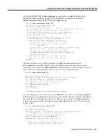
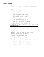
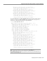
Verify that new interfaces are now in the correct state (shutdown). To do so on the
Cisco 7100 series, Cisco 7200 series, or Cisco uBR7200 series routers, use the show
interfaces serial 
slot/port command to display the specific interface, or use the show
interfaces
 command, without variables, to display the status of all interfaces in the
system.

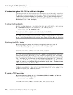
Cisco 7120

interface, followed by the type
(serial) and port adapter
number/interface port number

Router(config)# interface serial 3/0

Cisco 7140

interface, followed by the type

(serial) and port adapter
number/interface port number

Router(config)# interface serial 4/0

Table 8-1

Interface Subcommand Syntax (continued)

Platform

Command

Example

Содержание PA-2T3

Страница 1: ...etwork Registrar Packet PIX Point and Click Internetworking Policy Builder Precept RouteStream Secure Script ServiceWay SlideCast SMARTnet StreamView The Cell TrafficDirector TransPath ViewRunner VirtualStream VisionWay VlanDirector Workgroup Director and Workgroup Stack are trademarks Changing the Way We Work Live Play and Learn Empowering the Internet Generation The Internet Economy and The New ...

Страница 2: ......

Страница 3: ...nd six slot Cisco 7206 and Cisco 7206VXR Cisco uBR7200 series universal broadband routers Second generation Versatile Interface Processor VIP2 in Cisco 7500 series routers and Cisco 7000 series routers with the Cisco 7000 Series Route Switch Processor RSP7000 and Cisco 7000 Series Chassis Interface RSP7000CI Cisco 7100 series routers which consist of the Cisco 7120 and Cisco 7140 Catalyst Route Sw...

Страница 4: ...dware installation and maintenance information on the Catalyst 5000 series switches and the Catalyst RSM VIP2 refer to the following publications The installation and configuration guide that shipped with your Catalyst 5000 series switches Chapter 3 VIP2 and the PA T3 Port Adapter Provides instructions for installing the PA T3 port adapter on a VIP2 interface processor installed in Cisco 7500 or C...

Страница 5: ...y information for WAN interfaces for Cisco 7500 series Cisco 7000 series Cisco 7200 series Cisco 7100 series and Cisco uBR7200 series routers refer to the following publications Regulatory Compliance and Safety Information for the Cisco 7500 Series Routers Regulatory Compliance and Safety Information for the Cisco 7000 Series Routers Regulatory Compliance and Safety Information for the Cisco 7200 ...

Страница 6: ...ity none stop bits 1 and connection rates up to 28 8 kbps For a copy of CCO s Frequently Asked Questions FAQ contact cco help cisco com For additional information contact cco team cisco com If you are a network administrator and need personal technical assistance with a Cisco product that is under warranty or covered by a maintenance contract contact Cisco s Technical Assistance Center TAC at 800 ...

Страница 7: ...rovides one or two high speed serial PA T3 interfaces on Cisco 7100 series routers Cisco 7200 series routers Cisco uBR7200 series routers on the second generation Versatile Interface Processor VIP2 in all Cisco 7000 series and Cisco 7500 series routers and on the Catalyst RSM VIP2 in the Catalyst 5000 series switches See Figure 1 1 and Figure 1 2 Note Port adapters have a handle attached but this ...

Страница 8: ...eed interfaces on the Cisco 7200 series and Cisco uBR7200 series routers Serial network interfaces reside on modular port adapters which provide a direct connection between the high speed bus in the router and the external networks The PA T3 serial port adapter provides a full duplex synchronous serial PA T3 interface for transmitting and receiving data at rates of up to 34 megabits per second Mbp...

Страница 9: ...me Relay HDLC Switched Multimegabit Data Service SMDS and Point to Point Protocol PPP serial encapsulations Support for DS3 MIB RFC 1407 Support for remote and local loopback B3ZS line coding Scrambling and bandwidth reduction Online insertion and removal OIR Management Information Base Management Information Base MIB attributes are readable and writable across the Integrated Local Management Inte...

Страница 10: ...Management Information Base PA T3 Serial Port Adapter Installation and Configuration 1 4 ...

Страница 11: ...s to install a port adapter If you need additional equipment contact a service representative for ordering information PA T3 serial port adapter and one of the following VIP2 15 VIP2 20 VIP2 40 or VIP2 50 motherboard Catalyst RSM VIP2 15 or Catalyst RSM VIP2 40 motherboard Cisco 7100 series router with at least one available port adapter slot Cisco 7200 series router with at least one available po...

Страница 12: ... 16 CA or a later release of Cisco IOS Release 11 1 CA Cisco 7200 series Cisco 7204VXR and Cisco 7206VXR Cisco IOS Release 12 0 2 XE2 or a later release of Cisco IOS Release 12 0 XE Cisco IOS Release 12 0 3 T or a later release of Cisco IOS Release 12 0 T Cisco IOS Release 12 0 2 XE2 or a later release of Cisco IOS Release 12 0 XE Cisco IOS Release 12 0 3 T or a later release of Cisco IOS Release ...

Страница 13: ...on Guidelines which shipped with your Cisco 7200 series chassis and is also available on the Cisco Connection Documentation Enterprise Series CD ROM To determine if your Cisco 7000 series Cisco 7100 series Cisco 7500 series Cisco 7200 series or Cisco uBR7200 series router or Catalyst RSM VIP2 is compatible with the PA T3 serial port adapter use the show version command to display the current hardw...

Страница 14: ...00 series and Cisco 7500 series or Catalyst 5000 series switches and the midplane and is receiving power in the Cisco router The bus recognizes the port adapter If any of these conditions is not met or if the initialization fails for other reasons the enabled LED does not go on Table 2 2 LEDs for Uplink Port Status LED Color State Description ENABLED Green On Indicates that port adapter is ready f...

Страница 15: ...smissions is 1300 feet 396 meters Figure 2 3 PA T3 Serial Port Adapter Cable You can test the data terminal equipment to data circuit terminating equipment DTE to DCE cable connection by using the loopback dte command See the Using the loopback Command to Verify the Physical Interface section on page 8 24 for more information Interoperability Guidelines for PA T3 Serial Port Adapter DSUs The PA T3...

Страница 16: ...rporels Avant de travailler sur un équipement soyez conscient des dangers posés par les circuits électriques et familiarisez vous avec les procédures couramment utilisées pour éviter les accidents Pour prendre connaissance des traductions d avertissements figurant dans cette publication consultez le document Regulatory Compliance and Safety Information Conformité aux règlements et consignes de séc...

Страница 17: ...orna med elkretsar och känna till vanligt förfarande för att förebygga skador Se förklaringar av de varningar som förkommer i denna publikation i dokumentet Regulatory Compliance and Safety Information Efterrättelse av föreskrifter och säkerhetsinformation vilket medföljer denna anordning Electrical Equipment Guidelines Follow these basic guidelines when working with any electrical equipment Befor...

Страница 18: ... component to the factory immediately place it in a static shielding container Avoid contact between the printed circuit boards and clothing The wrist strap only protects components from ESD voltages on the body ESD voltages on clothing can still cause damage Never attempt to remove the printed circuit board from the metal carrier Caution For safety periodically check the resistance value of the a...

Страница 19: ...make certain the equipment and the television or radio are on circuits controlled by different circuit breakers or fuses Note The PA T3 serial port adapter has been designed to meet these requirements Modifications to this product that are not authorized by Cisco Systems Inc could void the various approvals and negate your authority to operate the product ...

Страница 20: ...FCC Class A Compliance PA T3 Serial Port Adapter Installation and Configuration 2 10 ...

Страница 21: ...l port adapter is used on the VIP2 in Cisco 7000 series and Cisco 7500 series routers and can be installed in either port adapter slot 0 or slot 1 on the VIP2 motherboard Note You can have up to three T3 serial interfaces on a VIP2 motherboard Cisco recommends a configuration of one PA T3 serial port adapter with one T3 serial interface and one PA 2T3 serial port adapter with two serial interfaces...

Страница 22: ...ached but this handle is not shown to allow a full view of detail on each port adapter s faceplate 24335 PA T3 in port adapter slot 0 PA T3 in port adapter slot 1 Port adapter handles not shown Bus connector DRAM SIMMs SRAM DIMM U5 CPU U6 U2 U4 Boot ROM EN ABLED R C VR XM TR R C LK AIS FER F R L O O F LL DS3 SERIAL EN ABLED R C VR XM TR R C LK AIS FER F R L O O F LL DS3 SERIAL R C LK AIS FER F R L...

Страница 23: ...install other port adapters on the VIP2 motherboard while the system is operating To install or replace port adapters first remove the VIP2 from its interface processor slot Note Each port adapter circuit board is mounted to a metal carrier and is sensitive to ESD damage The following procedures should be performed by a Cisco certified service provider only The VIP2 supports online insertion and r...

Страница 24: ...w port adapter installation or a port adapter replacement disconnect any interface cables from the ports on the front of the port adapter although this is not required You can remove VIP2s with cables attached however we do not recommend it Step 3 To remove the VIP2 from the chassis follow the steps in the section Removing a VIP2 in the configuration note Second Generation Versatile Interface Proc...

Страница 25: ...ort adapter for potential future use This completes the procedure for removing a new port adapter on a VIP2 Installing a Port Adapter Following is the standard procedure for installing a port adapter on the VIP2 Step 1 Remove the new port adapter from its antistatic container and position it at the opening of the slot Step 2 Carefully align the port adapter carrier between the upper and the lower ...

Страница 26: ...apter and slot mate properly position the carrier between the upper and the lower slot edges as shown in Figure 3 5 Step 3 Carefully slide the new port adapter into the port adapter slot until the connector on the port adapter is completely seated in the connector on the motherboard See Figure 3 6 Figure 3 6 Port Adapter Installed in a Port Adapter Slot Partial Port Adapter View Step 4 Replace the...

Страница 27: ...Adapter 3 7 Installing a Port Adapter This completes the procedure for installing a port adapter on a VIP2 Proceed to Chapter 8 Configuring the PA T3 Interfaces for information on how to configure your port adapter interfaces ...

Страница 28: ...Installing a Port Adapter PA T3 Serial Port Adapter Installation and Configuration 3 8 ...

Страница 29: ...s used on the Catalyst RSM VIP2 in the Catalyst 5000 series switches and can be installed in either port adapter slot 0 or slot 1 on the Catalyst RSM VIP2 motherboard Note You can have up to three T3 serial interfaces on a Catalyst RSM VIP2 motherboard Cisco recommends a configuration of one PA T3 serial port adapter with one T3 serial interface and one PA 2T3 serial port adapter with two serial i...

Страница 30: ...motherboard while the system is operating To install or replace port adapters first remove the Catalyst RSM VIP2 from the chassis Note Each port adapter circuit board is mounted to a metal carrier and is sensitive to ESD damage The following procedures should be performed by a Cisco certified service provider only The Catalyst RSM VIP2 supports online insertion and removal OIR but individual port ...

Страница 31: ...r Step 2 For a new port adapter installation or a port adapter replacement disconnect any interface cables from the ports on the front of the port adapter although this is not required You can remove the Catalyst RSM VIP2 with cables attached however we do not recommend it Step 3 To remove the Catalyst RSM VIP2 from the chassis follow the steps in the Route Switch Module Catalyst VIP2 15 and VIP2 ...

Страница 32: ... Attach an ESD preventive wrist strap between you and an unfinished chassis surface Note If you want to install a new port adapter on a Catalyst RSM VIP2 with a single port adapter you must first remove the blank port adapter from the port adapter slot in which you want to install the new port adapter Step 2 For a new port adapter installation or a port adapter replacement disconnect any interface...

Страница 33: ...are between the upper and the lower slot edges as shown in the cutaway in Figure 4 4 Caution To ensure a positive ground attachment between the port adapter carrier and the Catalyst RSM VIP2 motherboard and port adapter slot and to ensure that the connectors at the rear of the port adapter and slot mate properly position the carrier between the upper and the lower slot edges as shown in Figure 4 4...

Страница 34: ...Catalyst RSM VIP2 in the system follow the steps in the Route Switch Module Catalyst VIP2 15 and VIP2 40 Installation and Configuration Note Document Number 78 4780 01 which shipped with your Catalyst RSM VIP2 Step 6 If the interface cables have been disconnected reconnect the interface cables to the port adapters This completes the procedure for installing a port adapter on a Catalyst RSM VIP2 Pr...

Страница 35: ...d to install a new port adapter in a Cisco 7200 series router or replace a failed port adapter in the field In either case no tools are necessary all port adapters available for the Cisco 7200 series connect directly to the router midplane and are locked into position by a port adapter lever When removing and replacing a port adapter you need an antistatic mat onto which you can place a removed po...

Страница 36: ...e 5 2 Figure 5 2 Placing the Port Adapter Lever in the Unlocked Position Cisco 7206 Shown Step 3 Grasp the handle on the port adapter and pull the port adapter from the midplane about halfway out of its slot If you are removing a blank port adapter pull the blank port adapter completely out of the chassis slot Note As you disengage the port adapter from the router midplane OIR administratively shu...

Страница 37: ... position it at the opening of the slot See Figure 5 4 Step 2 Attach an ESD preventive wrist strap between you and an unfinished chassis surface Step 3 Use both hands to grasp the port adapter by its metal carrier edges and position the port adapter so that its components are downward See Figure 5 3 Step 4 Align the left and right edge of the port adapter metal carrier between the guides in the po...

Страница 38: ... not move to the locked position the port adapter is not completely seated in the midplane Carefully pull the port adapter halfway out of the slot reinsert it and move the port adapter lever to the locked position Figure 5 5 Placing the Port Adapter Lever in the Locked Position Cisco 7206 Shown This completes the procedure for installing a new port adapter in a Cisco 7200 series router Proceed to ...

Страница 39: ...1 Cisco uBR7200 Series with a PA T3 Port Adapter in Port Adapter Slot 2 Depending on the circumstances you might need to install a new port adapter or replace a failed port adapter in a Cisco uBR7200 series router In either case no tools are necessary all port adapters available for the Cisco uBR7200 series routers connect directly to the router midplane and are locked into position by a port adap...

Страница 40: ...port adapter Removing a Port Adapter Following is the procedure for removing a port adapter from a Cisco uBR7200 series router Step 1 Attach an ESD preventive wrist strap between you and an unfinished chassis surface Step 2 Place the port adapter retention clips or levers in the unlocked position For a Cisco uBR7246 place the port adapter retention clip for the desired port adapter slot in the unl...

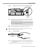
Страница 41: ...er halfway out of the slot disconnect all cables from the port adapter Step 5 After disconnecting the cables pull the port adapter from its chassis slot Caution Always handle the port adapter by the carrier edges and handle never touch the port adapter s components or connector pins See Figure 6 4 Figure 6 4 Handling a Port Adapter Step 6 Place the port adapter on an antistatic surface with its co...

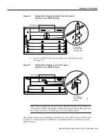
Страница 42: ...ide the port adapter halfway into the slot Caution Do not slide the port adapter all the way into the slot until you have connected all required cables Trying to do so disrupts normal operation of the router Step 5 With the port adapter halfway in the slot connect all required cables to the port adapter Step 6 After connecting the cables carefully slide the port adapter all the way into the slot u...

Страница 43: ...pter lever does not move to the locked position the port adapter is not completely seated in the midplane Carefully pull the port adapter halfway out of the slot reinsert it and move the port adapter lever to the locked position This completes the procedure for installing a port adapter in a Cisco uBR7200 series router Proceed to Chapter 8 Configuring the PA T3 Interfaces for information on how to...

Страница 44: ...Installing a Port Adapter PA T3 Serial Port Adapter Installation and Configuration 6 6 ...

Страница 45: ...red the system recognizes the new PA T3 port adapter interfaces and brings each of them up in their existing configuration After you verify that the new PA T3 port adapter is installed correctly the enabled LED goes on use the privileged level configure command to configure the new interfaces Be prepared with the information you need such as the following Protocols you plan to route on each new in...

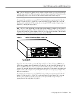
Страница 46: ...e Catalyst RSM VIP2 Cisco 7200 Series and Cisco uBR7200 Series Ports Physical port addresses specify the actual physical location of each interface port on a Cisco 7200 series router see Figure 8 1 or a Cisco uBR7200 series router see Figure 8 2 This address is composed of a two part number in the format port adapter slot number interface port number as follows The first number identifies the chas...

Страница 47: ...interface ports of a PA T3 port adapter in slot 2 of a Cisco uBR7200 series router The port adapter slots are numbered slot 1 and slot 2 for the Cisco uBR7246 and slot 1 for the Cisco uBR7223 slot 0 is always reserved for the Fast Ethernet port on the I O controller if present The individual interface port numbers always begin with 0 The number of additional ports depends on the number of ports on...

Страница 48: ...ssis slot port adapter interface port as follows The first number identifies the chassis slot in which the VIP2 is installed as shown in the sample system in Figure 8 3 The second number identifies the physical port adapter slot on the VIP2 and is either 0 or 1 The third number identifies the interface port on each PA T3 serial port adapter which is always numbered as interface 0 for the one port ...

Страница 49: ...dapter slot on the Catalyst RSM VIP2 and is either 0 or 1 The second number identifies the interface port on each PA T3 serial port adapter which is always numbered as interface 0 for the one port PA T3 serial port adapter and 0 or 1 for the two port PA T3 serial port adapter Figure 8 4 shows the port adapter slots and interface ports of a sample Catalyst 5509 switch On the Catalyst RSM VIP2 the f...

Страница 50: ...ce resides and the port number is the physical port Interfaces in the Cisco IOS software are identified by a type slot number and port number For example serial 3 1 indicates port 1 on the serial port adapter in slot 3 Slots in the Cisco 7120 series routers are numbered as shown in Figure 8 5 The fixed LAN interface is slot 0 the fixed WAN interface is slot 1 and the modular port adapter interface...

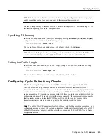
Страница 51: ...tructions Step 2 At the privileged level prompt enter configuration mode and specify that the console terminal is the source of the configuration subcommands as follows Router configure terminal Enter configuration commands one per line End with Crtl Z Router config Step 3 Specify the slot port address of the first interface that you want shut down by entering the subcommand interface as described...

Страница 52: ...terface serial 1 1 1 Router config if shutdown Ctrl Z Router The example that follows is for a Catalyst RSM VIP2 Router config if interface serial 1 0 Router config if shutdown Router config if interface serial 1 1 Router config if shutdown Ctrl Z Router Step 6 Write the new configuration to memory as follows Router copy running config startup config OK Router The system displays an OK message whe...

Страница 53: ...hat new interfaces are now in the correct state shutdown on a Catalyst RSM VIP2 use the show interfaces serial port adapter interface command to display the specific interface or use the show interfaces command without variables to display the status of all interfaces in the system The example that follows is for a Catalyst RSM VIP2 Router show interfaces serial 1 0 Serial 1 0 is administratively ...

Страница 54: ...ocumentation section on page vi Performing a Basic Configuration The following steps make up a basic interface configuration for the PA T3 serial port adapter Press the Return key after each step unless otherwise noted At any time you can exit the privileged level and return to the user level by entering disable at the prompt router disable router Step 1 At the privileged level prompt enter config...

Страница 55: ...nfiguration mode choose the internal clock source by entering the clock source configuration subcommand as in the following example router config if clock source internal Use the no form of this command to restore the default clock source which is line Step 5 In interface configuration mode change the shutdown state to up and enable the interface as follows router config if no shutdown Step 6 Conf...

Страница 56: ...SU Mode In interface configuration mode define the DSU interoperability mode by entering the dsu mode 0 1 2 configuration subcommand as in the following example router config if dsu mode 1 Use the no form of this command to return to the default which is 0 Note The local port configuration must match the remote port configuration For example if you define the DSU interoperability mode as 1 on the ...

Страница 57: ...if cablelength 250 Use the no form of this command to return to the default which is 10 feet Configuring Cyclic Redundancy Checks The PA T3 serial port adapter uses a 16 bit CRC by default it also supports a 32 bit CRC CRC is an error checking technique that uses a calculated numeric value to detect errors in transmitted data The sender of a data frame divides the bits in the frame message by a pr...

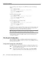
Страница 58: ... and use the no crc 32 command For complete command descriptions and instructions refer to the related software documentation Note When enabling a 32 bit CRC on an interface ensure that the remote device is also configured for a 32 bit CRC Both the sender and the receiver must use the same CRC setting To check the interface configuration using show commands proceed to the following section Checkin...

Страница 59: ...the correct slot number For a VIP2 specify information that is specific to the new serial interface with the show controllers serial slot port adapter interface command and verify that the first line of the display specifies the interface with the correct slot number For a Catalyst RSM VIP2 specify information that is specific to the new serial interface with the show controllers serial port adapt...

Страница 60: ...res 0 output buffers swapped out 1 carrier transitions rxLOS inactive rxLOF inactive rxAIS inactive txAIS inactive rxRAI inactive txRAI inactive router For a VIP2 the show interfaces type slot port adapter port command displays status information including the physical slot and port address for the interfaces you specify In this example a one port PA T3 serial port adapter configured VIP2 is in ch...

Страница 61: ...isco 7200 series and Cisco uBR7200 series routers use the show controllers command to display all the current interface processors and their interfaces Following is an example of the show controllers command that shows serial port 2 0 on a one port PA T3 serial port adapter installed in chassis slot 2 for a Cisco 7200 series router router show controllers 2 0 M1T Serial show controller PAS unit 0 ...

Страница 62: ...t Severely Err Secs 0 Severely Err Framing Secs 0 Unavailable Secs 86400 Line Errored Secs 0 C bit Errored Secs 0 C bit Severely Errored Secs Transmitter is sending remote alarm Receiver has loss of signal Last FEAC code received LOS FEBE since last read 0 F bit errors since last read 24 M bit errors since last read 2 PIO A 738 PIO B 60B Gapper register 1094 Framer register information reg 0 C0 re...

Страница 63: ...ode 0 Cable length is 50 Data in current interval 325 seconds elapsed 0 Line Code Violations 0 P bit Coding Violation 0 C bit Coding Violation 0 P bit Err Secs 0 P bit Severely Err Secs 0 Severely Err Framing Secs 0 Unavailable Secs 0 Line Errored Secs 0 C bit Errored Secs 0 C bit Severely Errored Secs Total Data last 24 hours 0 Line Code Violations 0 P bit Coding Violation 0 C bit Coding Violatio...

Страница 64: ...V M Version 11 1 16 CA Synced to mainline version 11 1 13 5 Copyright c 1986 1997 by cisco Systems Inc Compiled Sat 06 Sep 97 02 12 by paking Image text base 0x60010900 data base 0x60A42000 ROM System Bootstrap Version 5 3 2 3 2 kmac 3 2 MAINTENANCE INTERIM SOFTWARE ROM GS Software Version 11 1 8 CA EARLY DEPLOYMENT RELEASE SOFTWARE fc1 keats uptime is 22 minutes System restarted by reload System ...

Страница 65: ...shows a one port PA T3 serial port adapter in chassis slot 10 on a VIP2 router show diag 10 Slot 10 Physical slot 10 physical slot 0x5 logical slot 10 CBus 0 Microcode Status 0x4 Master Enable LED WCS Loaded Board is analyzed Pending I O Status None EEPROM format version 1 VIP2 controller HW rev 2 4 board revision D0 Serial number 04481599 Part number 73 1684 03 Test history 0x00 RMA number 00 00 ...

Страница 66: ... a VIP2 use the show controllers cbus command to display all of the current interface processors and their interfaces Following is an example of the show controllers cbus command that shows serial port 1 0 0 on a one port PA T3 serial port adapter installed on a VIP2 in chassis slot 1 router show controllers cbus 1 0 0 MEMD at 40000000 2097152 bytes unused 4288 recarves 1 lost 0 RawQ 48000100 Retu...

Страница 67: ...pcbufQ_classic 48000158 8 items 4096 bytes 3570 buffer headers 48002000 4800FF10 pool0 9 buffers 256 bytes queue 48000140 pool1 458 buffers 1536 bytes queue 48000148 pool2 229 buffers 4512 bytes queue 48000168 pool3 4 buffers 4544 bytes queue 48000170 slot0 VIP2 hw 2 4 sw 21 40 ccb 5800FF20 cmdq 48000080 vps 8192 software loaded from system IOS tm VIP Software SVIP DW M Version 11 1 16 CA ROM Moni...

Страница 68: ...ection failed Following is an example of a successful ping command to a remote server with the address 10 0 0 0 router ping 10 0 0 0 Return Type escape sequence to abort Sending 5 100 byte ICMP Echoes to 10 0 0 0 timeout is 2 seconds Success rate is 100 percent 5 5 round trip min avg max 1 15 64 ms router If the connection fails verify that you have the correct IP address for the server and that t...

Страница 69: ...ore the framer Set the interface into network payload loopback mode as follows Router configure terminal Enter configuration commands one per line End with CNTL Z router config interface serial 6 0 router config if loopback network payload Network payload loopback loops just the payload data back toward the network at the PA T3 framer Set the interface into remote loopback mode as follows Router c...

Страница 70: ...Checking the Configuration PA T3 Serial Port Adapter Installation and Configuration 8 26 ...

Страница 71: ...Adapter page 7 3 Overview The PA T3 serial port adapter can be installed in port adapter slot 3 in Cisco 7120 series routers and in port adapter slot 4 in Cisco 7140 series routers Figure 7 1 shows port adapter slot 3 of a Cisco 7120 series router Figure 7 2 shows port adapter slot 4 of a Cisco 7140 series router Figure 7 1 Cisco 7120 Series Router Port Adapter Slot 3 Location SLOT 0 SLOT 1 0 2 FE...

Страница 72: ... the procedure for removing a port adapter from a Cisco 7100 series router Step 1 Attach an ESD preventive wrist strap between you and the chassis See Figure 7 1 or Figure 7 2 for the location of the ESD plug Step 2 Use a number 2 Phillips screwdriver to loosen the screws on the locking tab then slide the tab down to the unlocked position See Figure 7 1 or Figure 7 2 Step 3 Grasp the handle on the...

Страница 73: ... a Cisco 7100 series router Step 1 Attach an ESD preventive wrist strap between you and the chassis See Figure 7 1 for the location of the ESD plug Step 2 Ensure that the locking tab is down in the unlocked position If it is locked use a number 2 Phillips to loosen the screws then slide the tab down to the unlocked position See Figure 7 1 or Figure 7 2 Step 3 Remove the new port adapter from its a...

Страница 74: ... router slide the locking tab up to the locked position and tighten the screws Figure 7 1 or Figure 7 2 shows the locking tab in the locked position Note If the port adapter lever is not in the locked position the port adapter is not completely seated in the router Carefully pull the port adapter halfway out of the slot reinsert it and move the port adapter lever to the locked position This comple...

Отзывы: