background image

Step 3

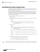
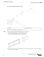
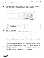
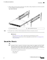
Attach the chassis with the installed rack-mount bracket to the rack using the screws that work for your rack.

What to do next

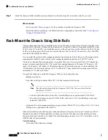
• See

Ground the Chassis, on page 9

for the procedure to ground the Firepower 2100.

• Install the cables according to your default software configuration as described in the

Cisco Firepower

Getting 2100 Started Guide

.

Rack-Mount the Chassis Using Slide Rails

This procedure describes how to install the Firepower 2100 series in a rack using slide rails. It applies to all
models of the 2100 series. It ships with the Firepower 2130 and 2140 chassis; it is optional for the 2110 and
2120. For the 2110 and 2120, you install three screws on the chassis to secure the slide rail. For the 2130 and
2140, you use the pegs on the chassis to secure the slide rail. See

Product ID Numbers

for a list of the PIDs

associated with racking the chassis.

You can install the optional cable management bracket on all models of the 2100 series. The optional cable
management bracket kit comes with two cable management brackets and four 8-32x0.375"L screws.

The rack is a standard Electronic Industries Association (EIA) rack. It is a 4-post-EIA-310-D, which is the
current revision as specified by EIA. The vertical hole spacing alternates at .50 inches (12.70 mm) to .625
inches (15.90 mm) to .625 inches (15.90 mm) and repeats. The start and stop space is in the middle of the
.50-inch holes. The horizontal spacing is 18.312 inches (465.1 mm), and the rack opening is specified as a
minimum of 17.75 inches (450 mm).

You need the following to install the Firepower 2100 in a rack using slide rails:

• Phillips screwdriver

• One slide rail kit (part number 800-103711-01) that contains the following:

The slide rail kit ships with the Firepower 2130/2140. You can order it for the
Firepower 2110/2120.

Note

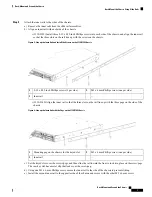
• Left and right slides rails with two M3 x 6-mm Phillips screws (part number 48-101144-01)

• Two slide rail locking brackets (700-105350-02) with six 8-32 x 0.25-inch Phillips screws (part

number 48-101429-01)

• (Optional) Two cable management brackets (part number 700-106377-01) with four 8-32 x 0.375-inch

Phillips screws (part number 48-2696-01)

Slide rail assemblies work with four-post racks and cabinets with square slots, round 7.1mm holes, #10-32
threaded holes, and #12-24 threaded holes on the rack post front. The slide rail works with front to back
spacing of rack posts from 24 to 36 inches. The rack-mounting posts need to be 2 to 3.5-mm thick to work
with the slide rail rack mounting.

Safety Warnings

Take note of the following warnings:

Rack-Mount and Ground the Chassis

4

Rack-Mount and Ground the Chassis

Rack-Mount the Chassis Using Slide Rails

Содержание Firepower 2100 Series

Страница 1: ...ustomer service representative immediately Note See Package Contents for a list of what shipped with the chassis Step 1 Remove the chassis from its cardboard container and save all packaging material Step 2 Compare the shipment to the equipment list provided by your customer service representative Verify that you have all items Step 3 Check for damage and report any discrepancies or damage to your...

Страница 2: ...ackets part number 700 106374 01 with six 8 32 x 0 281 inch screws part number 48 101518 01 The rack mount brackets ship with the Firepower 2110 2120 and are orderable for the Firepower 2130 2140 Note Rack mount screws The rack mount screws ship with the Firepower 2110 2120 and are orderable for the Firepower 2130 2140 Note Four 12 24 x 0 75 inch Phillips screws part number 648 0440 01 for securin...

Страница 3: ...k mount bracket a Install the cable management screws into the rack mount bracket Figure 2 Install the Cable Management Screws into the Rack Mount Bracket b Install two 8 32 x 0 375 inch screws through the inside of each rack mount bracket to secure the cable management bracket to the rack mount bracket Rack Mount and Ground the Chassis 3 Rack Mount and Ground the Chassis Rack Mount the Chassis Us...

Страница 4: ...cal hole spacing alternates at 50 inches 12 70 mm to 625 inches 15 90 mm to 625 inches 15 90 mm and repeats The start and stop space is in the middle of the 50 inch holes The horizontal spacing is 18 312 inches 465 1 mm and the rack opening is specified as a minimum of 17 75 inches 450 mm You need the following to install the Firepower 2100 in a rack using slide rails Phillips screwdriver One slid...

Страница 5: ...ound conductor or operate the equipment in the absence of a suitably installed ground conductor Contact the appropriate electrical inspection authority or an electrician if you are uncertain that suitable grounding is available Warning Statement 1030 Equipment Installation Only trained and qualified personnel should be allowed to install replace or service this equipment Warning Statement 1047 Ove...

Страница 6: ...bracket a Install the cable management screws into the slide rail locking bracket Figure 4 Install the Cable Management Screws into the Slide Rail Locking Bracket b Install two 8 32 x 0 375 inch Phillips screws through the inside of the slide rail locking bracket to secure the cable management bracket to slide rail locking bracket Rack Mount and Ground the Chassis 6 Rack Mount and Ground the Chass...

Страница 7: ...t the three slots on the rail line up with the three pegs on the side of the chassis Figure 6 Line up the Inner Rail with the Pegs on the 2130 2140 Chassis M3 x 6 mm Phillips screw one per side 2 Mounting peg on the chassis for the keyed slot 1 Inner rail 3 c Set the keyed slots over the screws pegs and then slide the rail toward the front to lock it in place on the screw pegs The rear key slot ha...

Страница 8: ...ing pegs into the rack post holes from the outside front c Press the securing plate release button marked PUSH The spring loaded securing plate closes to lock the pegs in place d Adjust the slide rail length and then push the rear mounting pegs into the corresponding rear rack post holes The slide rail must be level front to rear The rear mounting pegs enter the rear rack post holes from the insid...

Страница 9: ...es according to your software configuration as described in the Cisco Firepower 2100 Getting Started Guide Ground the Chassis Grounding the chassis is required even if the rack is already grounded A grounding pad with two threaded M4 holes is provided on the chassis for attaching a grounding lug The grounding lug must be Nationally Recognized Testing Laboratory NRTL listed In addition a copper con...

Страница 10: ...e appropriate electrical inspection authority or an electrician if you are uncertain that suitable grounding is available Warning Statement 1046 Installing or Replacing the Unit To reduce risk of electric shock when installing or replacing the unit the ground connection must always be made first and disconnected last Warning Statement 1025 Use Copper Conductors Only To reduce risk of fire use copp...

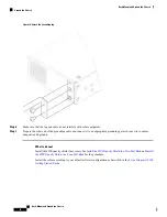
Страница 11: ...dhesive label from the grounding pad on the chassis Step 5 Place the grounding lug against the grounding pad so that there is solid metal to metal contact and insert the two screws with washers through the holes in the grounding lug and into the grounding pad Rack Mount and Ground the Chassis 11 Rack Mount and Ground the Chassis Ground the Chassis ...

Страница 12: ...re adequate earth ground What to do next Install the FIPS opacity shield if necessary See Install the FIPS Opacity Shield in a Two Post Rack and Install the FIPS Opacity Shield in a Four Post Rack for the procedure Install the cables according to your default software configuration as described in the Cisco Firepower 2100 Getting Started Guide Rack Mount and Ground the Chassis 12 Rack Mount and Gr...

Отзывы: