Norman Network Protection
quick setup guide
For the latest setup guide,
please visit www.norman.com
Norman Network Protection
quick setup guide
For the latest setup guide,
please visit www.norman.com
1
2
3
4
5
6
7
8
Introduction to Norman Network Protection Appliance
The Norman Network Protection Appliance provides a front-end protection solution
for your entire local area network or segment of your internal network.
Norman Network Protection is powered by Linux and provides additional security by
using the Norman SandBox technology.
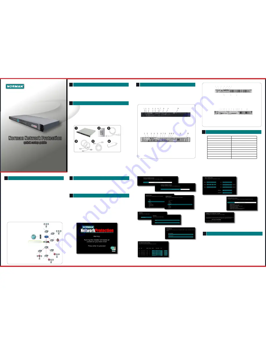
Checking the Package Contents
You will find the following items in your Network Protection Appliance package:
1. Norman Network Protection Appliance
2. A quick setup guide (this document)
3. An AC power cable
4. Two (2) category 6 ethernet standard cable (color “Green”)
5. One (1) category 6 ethernet standard cable (color ”Blue”)
6. A bootable USB memory stick containing recovery software
(Behind the frontbezel)
If an item is missing from the package, contact your reseller immediately.
Appliance Overview
The Norman Network Protection Appliance consists of three (3) Network Interface
Cards. The NICs (named “Eth1” and “Eth2”) are used for traffic inspection (inside and
outside interfaces). These interfaces do not need any IP-address
The third interface (named “Eth0”) is used as an interface towards the Linux console,
the NNP command line console and the web administration interface. This interface
needs an IP-address.
Front R210
1. Power-on indicator,
power button
2. NMI button
3. USB connectors (2)
1. iDRAC6 Enterprise port
(optional)
2. VFlash media slot
3. Serial connector
4. PCIe slot 1
Power up your Network Protection Appliance
1. Connect the power cable from the power source (typically an UPS) to the power
jack (while facing the back of the appliance). The power cable is included with the
appliance packaging.
Basic Configuration for the Network Protection Appliance
IMPORTANT: Do not connect the in and out interfaces to your network
before you have completed the configuration.
1. Connect a monitor and an USB-keyboard to the Network Protection Appliance.
2. Power up the Network Protection Appliance.
3. When the device has finished booting up follow the instructions as described
below. When asked, use the details from your “Network Planning Worksheet” as
described in chapter 4.
If you have been provided a newer NNP version as ISO image or on USB please
follow the instructions provided.
Press 1 or Enter to start the installation.
Completing the Web based Setup Wizard
IMPORTANT: Do not power up the appliance before connecting
it to the network.
1. Connect only the Admin interface to the appropiate switch in your
network. Make sure this is accessible from your network, and that it
is not connected behind the “Eth1” interface.
2. From another computer connect to the IP-address of the appliance
on port 2868.
Example: http://<Network Protection Appliance-IP>:2868
3. Your are now prompted for a username and password.
5. After finishing the configuration wizard connect the device to the network as
described in the next chapter
Checking installation archives
The installer will check the
integrity of the installation
archive.
Keyboard
layout
Select your
keyboard
layout, then
click
Next
.
Timezone
Select your timezone
by first selecting your
continent, then your
country.
Root password
Enter your desired password. This
password is the same for both the web
based admin interface, and the Linux
console, so please don’t lose it.
Configuring the network cards
NNP appliance comes with four NICs, but only three
will be used in this round. To assist you in identify-
ing the NICs you can use the
Identify
function.
When pressing this button the LEDs on the corre-
sponding NIC will start blinking, correctly identifying
the NIC to the ethx.
The default for NNP NIC configuration is one admin
NIC and two Bridge NICs.
Admin interface setup
To be able to manage your NNP
an IP-address is necessary. Now
it’s time to use your Network
Planning Worksheet. Insert the
details in the appropriate fields.
Installing files from archive
The installation will resume.
Click
Details
to see a more
verbose output.
Complete
Congratulations, your installation
is done. Click
Reboot
to finish
and start your NNP.
Norman Network Protection
Back R210
Back R610
Front R610
Network Planning Worksheet
Host name:
. . .
Network Protection Primary IP address:
. . .
Network Protection subnet:
. . .
Default Gateway:
. . .
DNS Suffix:
. . .
DNS Server 1:
. . .
DNS Server 2:
. . .
Network speed:
. . .
Duplex (inside NIC):
. . .
Duplex (outside NIC):
. . .
5. Video connector
6. USB connectors (2)
7. PCIe slot 2
8. Ethernet connectors (4)
4. Video connector
5. LCD menu buttons
6. LCD panel
7. System identification button
8. Hard drives (6)
9. Optical drive (optional)
10. System identification panel
9. System status indicator connector
10. System status indicator
11. System identification button
12. Power supply 1 (PS1)
13. Power supply 2 (PS2)
1 Power-on indicator, power button
2 NMI button
3 Video connector
4 Hard drive activity indicator
5 Diagnostic indicator lights (4)
6 System status indicator
7 System identification button
8 USB connectors (2)
9 System identification panel
10 Optical drive (optional)
1 iDRAC6 Enterprise port (optional)
2 VFlash media slot (optional)
3 Ethernet connectors (2)
4 serial connector
5 video connector
6 eSATA
7 USB connectors (2)
8 Ethernet connectors (2)
9 System status indicator light
10 System identification button
11 System identification connector
12 Power supply
13 Retention clip
The Norman Network Protection Appliance can be deployed almost anywhere in
your network. If you already know where to place the Norman Network
Protection Appliance please skip this part, and go on to chapter 6.
If you are uncertain where to deploy the Norman Network Protection Appliance
please consider one of the below scenarios.
1. Scan traffic to/from the Internet
In this deployment scenario Norman Network Protection scans supported
traffic to/from the Internet.
2. Scan traffic to/from an DMZ
In this deployment scenario Norman Network Protection scans supported traffic to/
from the DMZ from both the internal LAN and Internet.
3. Scan traffic between LANs or segments
In this deployment scenario Norman Network Protection scans supported traffic to/
from the Internet in addition to traffic to/from computers from different segments.
4. Scan traffic in one or
more VLAN(s):
In this deployment scenario
Norman Network Protection
scans supported traffic com-
ming from VLAN computers
marked with red, in addition
to traffic going to/from seg-
ments on each side of the
router.
Deployment Strategy


