background image


9

Installing Hard Disk Drives in the Cisco Wide Area Application Engine 611

78-17404-01

  Removing and Replacing a SCSI Hard Disk Drive

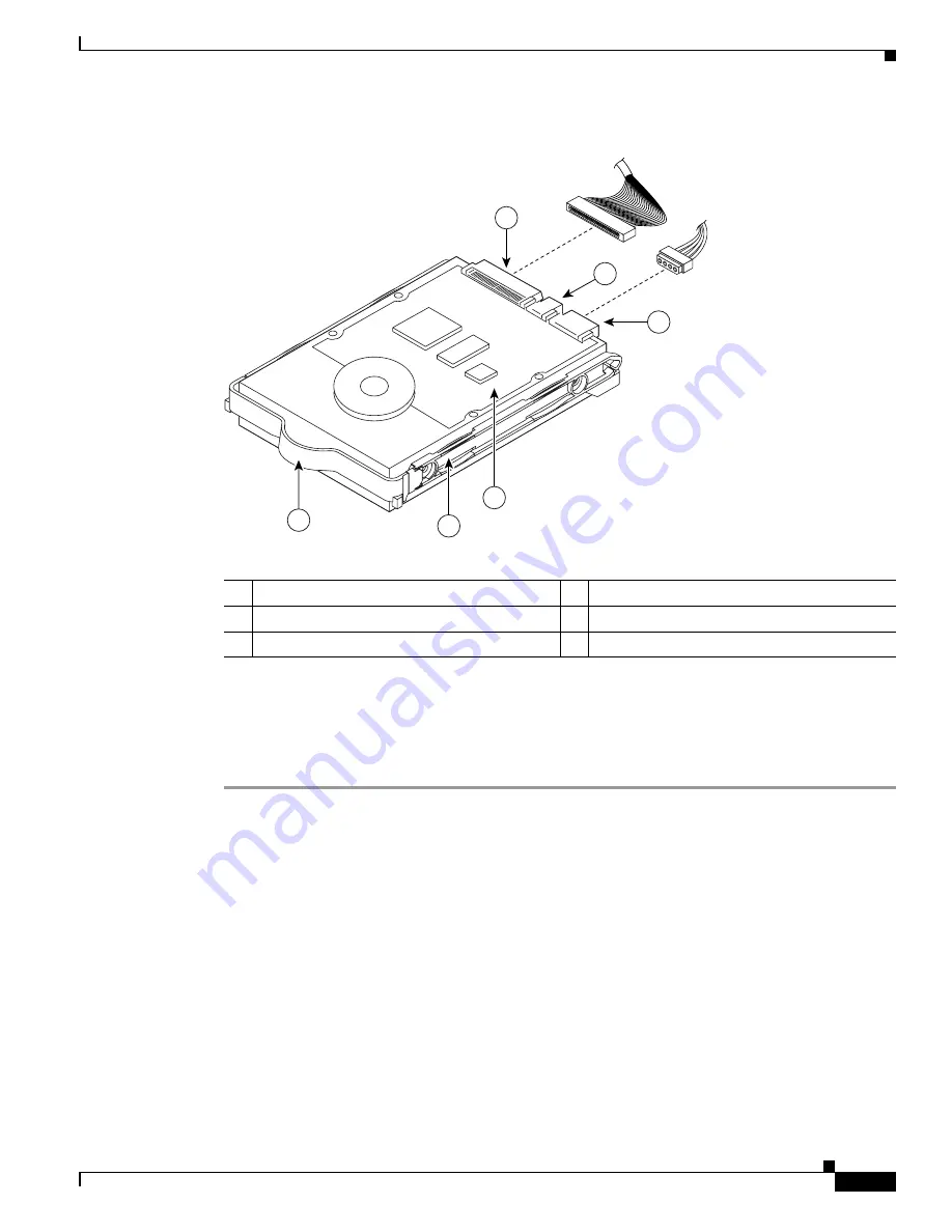
Figure 5

Disk Drive Orientation During Installation

Step 11

Connect the power and SCSI cables to the drive. If you disconnected the IDE cable to the CD-ROM, 
reconnect it. 

Step 12

Make sure that your cables are lying flat inside the chassis, so that you do not shear them when you 
replace the chassis cover.

1

SCSI connector

2

Jumper pins

3

Power connector

4

Circuit board facing up

5

Drive carrier

6

Carrier handle

151557

1

3

2

5

4

6

Содержание DISK-611SC-144GB=

Страница 1: ...his publication contains the following sections Safety Overview page 1 Introduction page 3 Removing the Bezel and Cover page 4 Assigning SCSI IDs page 6 Removing and Replacing a SCSI Hard Disk Drive page 7 Replacing the Cover and Bezel and Completing the Installation page 10 Obtaining Documentation page 11 Cisco Product Security Overview page 11 Obtaining Technical Assistance page 12 Note For tran...

Страница 2: ...ines Before installing your device in a rack review the following guidelines Two or more people are required to install the device in a rack Ensure that the room air temperature is below 95 F 35 C Do not block any air vents usually 6 inches 15 cm of space provides proper airflow Plan the device installation starting from the bottom of the rack Install the heaviest device in the bottom of the rack ...

Страница 3: ...lank faceplates and cover panels serve three important functions they prevent exposure to hazardous voltages and currents inside the chassis they contain electromagnetic interference EMI that might disrupt other equipment and they direct the flow of cooling air through the chassis Do not operate the system unless all cards faceplates front covers and rear covers are in place Statement 1029 Warning...

Страница 4: ... the ground connection must always be made first and disconnected last Statement 1046 To remove the bezel and cover follow these steps Step 1 Review the information in the Protecting Against Electrostatic Discharge section on page 2 Step 2 Power down the device and all attached devices Disconnect the power cord and all external cables Step 3 Remove the bezel as shown in Figure 1 a Press the releas...

Страница 5: ...ling and airflow replace the cover before turning on the device Operating the device for extended periods over 30 minutes with the cover removed might damage device components Step 6 Before you begin working inside the chassis familiarize yourself with the location of the components that you will be handling Figure 3 shows the front of the chassis and the location of the drive bays behind the beze...

Страница 6: ...s on the appropriate jumper pins as follows Hitachi disks have a single set of jumpers Follow these jumper settings instructions for Hitachi disks Assign SCSI ID 0 to the disk drive in the first drive bay by removing any jumpers from the jumper pins The first drive bay drive bay 0 is located below the CD ROM drive on the left side of your system See Figure 3 Assign SCSI ID 1 to the disk drive in t...

Страница 7: ...e second drive bay drive bay 1 is located below the flash memory card on the right side of your system See Figure 3 Figure 4 shows the connector end of the hard disk drive and the location of the jumper pins Figure 4 Hard Disk Drive Connectors and SCSI ID Jumper Pins Step 2 To check whether the configuration is correct refer to the boot time messages on the device console An example is as follows ...

Страница 8: ...ee Figure 2 Step 6 To remove the hard disk drive in either drive bay work from inside the chassis and disconnect the SCSI cable from the hard disk drive by using your thumbs to work the cable connector out of the drive connector Do not pull directly on the cable itself Tip To remove the hard disk drive in the first bay the bay on the left below the CD ROM drive begin by disconnecting the integrate...

Страница 9: ...ation Step 11 Connect the power and SCSI cables to the drive If you disconnected the IDE cable to the CD ROM reconnect it Step 12 Make sure that your cables are lying flat inside the chassis so that you do not shear them when you replace the chassis cover 1 SCSI connector 2 Jumper pins 3 Power connector 4 Circuit board facing up 5 Drive carrier 6 Carrier handle 151557 1 3 2 5 4 6 ...

Страница 10: ...our installation follow these steps Step 1 Install the cover Place it into position slide it forward and then tighten the captive screw labeled 1 in Figure 2 Caution Before sliding the cover forward make sure that the cover will properly engage the ledge at the front of the device Step 2 Install the bezel as follows a Align the hooks on the bottom of the bezel with the device b Press the bezel tow...

Страница 11: ...ese tasks Report security vulnerabilities in Cisco products Obtain assistance with security incidents that involve Cisco products Register to receive security information from Cisco A current list of security advisories and notices for Cisco products is available at this URL http www cisco com go psirt If you prefer to see advisories and notices as they are updated in real time you can access a Pr...

Страница 12: ...contact your reseller Cisco Technical Support Documentation Website The Cisco Technical Support Documentation website provides online documents and tools for troubleshooting and resolving technical issues with Cisco products and technologies The website is available 24 hours a day at this URL http www cisco com techsupport Access to all tools on the Cisco Technical Support Documentation website re...

Страница 13: ... service request is assigned to a Cisco engineer The TAC Service Request Tool is located at this URL http www cisco com techsupport servicerequest For S1 or S2 service requests or if you do not have Internet access contact the Cisco TAC by telephone S1 or S2 service requests are those in which your production network is down or severely degraded Cisco engineers are assigned immediately to S1 and S...

Страница 14: ... 2 S2 Operation of an existing network is severely degraded or significant aspects of your business operation are negatively affected by inadequate performance of Cisco products You and Cisco will commit full time resources during normal business hours to resolve the situation Severity 3 S3 Operational performance of your network is impaired but most business operations remain functional You and C...

Страница 15: ...go Cisco IOS Cisco Press Cisco Systems Cisco Systems Capital the Cisco Systems logo Cisco Unity Enterprise Solver EtherChannel EtherFast EtherSwitch Fast Step Follow Me Browsing FormShare GigaDrive HomeLink Internet Quotient IOS iPhone IP TV iQ Expertise the iQ logo iQ Net Readiness Scorecard iQuick Study LightStream Linksys MeetingPlace MGX Networkers Networking Academy Network Registrar PIX ProC...

Страница 16: ...16 Installing Hard Disk Drives in the Cisco Wide Area Application Engine 611 78 17404 01 Obtaining Technical Assistance ...

Отзывы: