background image

7


Getting Started and Product Document of Compliance for the Cisco Catalyst IW6300 Heavy Duty Series Access Points

Grounding the Device

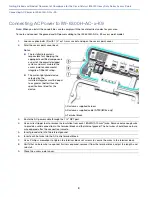
1.

If using insulated 6-AWG (13.3 mm

2

) copper ground wire, strip the insulation as required for the grounding lug.

2.

Use the appropriate crimping tool to crimp the 
bare 6-AWG (13.3 mm

2

) copper ground wire to 

the supplied grounding lug.

Note: 

The grounding lug and hardware used 

must comply with local and national electrical 
codes.

3.

Open the anti-corrosion sealant (supplied), and 
apply a liberal amount over the metal surface, 
called the Ground Pad, where the ground strap 
screw holes are located.

1—Ground pad

4.

Connect the grounding lug to the access point 
grounding screw holes using the supplied two 
Phillips head screws (M4 x10 mm) with lock 
washers. Tighten the grounding screw to 22 to 
24 lb-in (2.49 to 2.71 Nm).

5.

If necessary, strip the other end of the ground wire and connect it to a reliable earth ground, such as a grounding 
rod or an appropriate grounding point on a metal streetlight pole that is grounded.

332163

520005

1

520006

Содержание Catalyst IW-6300H-AC K9 Series

Страница 1: ...ion Statements for Hazardous Locations Environments page 4 Additional Considerations Before Installation page 6 Grounding the Device page 6 Connecting AC Power to IW 6300H AC x K9 page 8 Connecting DC Power to IW 6300H DCW x K9 page 9 Connecting DC Power to IW 6300H DC x K9 page 10 Antennas page 11 Avoidance of Electrostatic Discharge page 11 Performing Maintenance page 11 Removing the Access Poin...

Страница 2: ...ower model IW 6300H DC x K9 DC power model IW 6300H DCW x K9 DC wide range power model Mounting kit IOT ACCPMK Ground lug and screws with lock washers Weatherization tape and anti seize compound This document Part Number 78 101483 01 Optional Tools and Hardware The optional tools and hardware that can be obtained from Cisco are Optional power injector AIR PWRINJ 60RGDx Antennas 2 4 5 GHz refer to ...

Страница 3: ... know your device install and configure it as well as access software You will see the following categories as well as other important information All support information for Cisco Catalyst IW6300 Heavy Duty Series Access Points Provides the most requested resources and a list of all of the models in the series Release and General Information Links to the Software Download site Compatibility Infor...

Страница 4: ...oduct should be handled according to all national laws and regulations Statement 1040 Warning For connections outside the building where the equipment is installed the following ports must be connected through an approved network termination unit with integral circuit protection 10 100 1000 Ethernet Statement 1044 Warning When installing or replacing the unit the ground connection must always be m...

Страница 5: ... unit operation perform POST on the device in a nonhazardous location before installation Statement 108 Caution This equipment is suitable for use in Class I Division 2 Groups A B C D or non hazardous locations Note This equipment is rated as following DC maximum operating range 44 to 57VDC 1 2A DC wide range maximum operating range 10 8 to 36VDC 5 9A AC maximum operating range 85 264V marked 100 ...

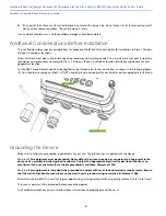
Страница 6: ...o be applied to the threads prior to the installation as shown in the following figure 1 You should also supply certified 1 2 NPT conduit gland and adapter for each port used for appropriate installation Grounding the Device Make sure to follow any grounding requirements at your site The ground lug is supplied with the device Warning This equipment must be grounded Never defeat the ground conducto...

Страница 7: ...and national electrical codes 3 Open the anti corrosion sealant supplied and apply a liberal amount over the metal surface called the Ground Pad where the ground strap screw holes are located 1 Ground pad 4 Connect the grounding lug to the access point grounding screw holes using the supplied two Phillips head screws M4 x10 mm with lock washers Tighten the grounding screw to 22 to 24 lb in 2 49 to...

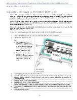
Страница 8: ...ting The water tight gland device selected by the installer integrator must be equal to or greater better than the specifications listed for the device 1 Customer supplied harness 2 Customer supplied cable ATEX IECEx only 3 Terminal block 3 Route the AC power cable through the 1 2 NPT port 4 Use a wire stripper tool to remove the insulation from each 18 AWG 0 75mm2 wire Remove only enough wire to ...

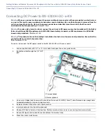
Страница 9: ... the ground and DC power cabling to the IW 6300H DCW x K9 access point 1 Loosen captive bolts 1 with 1 2 or 13 mm socket and open the access point cover 2 Fold the access point cover back Notes The installer integrator is responsible for supplying the appropriate certified components as part of the overall designed system and must maintain the access point environmental integrity of IP66 67 rating...

Страница 10: ... standards or ES1 requirements in IEC 62368 based safety standards Statement 1033 Warning This product relies on the building s installation for short circuit overcurrent protection Ensure that the protective device is rated not greater than 10A Statement 1005 To route and connect the DC power cable to the IW 6300H DC x K9 access point 1 Loosen captive bolts with 1 2 or 13 mm socket and open the a...

Страница 11: ...o continuously drain off electrostatic charges in the installation Performing Maintenance The access point requires minimal periodic or preventive maintenance as it has no moving parts filters lubricants or mechanical contact components However when installed in a hazardous location periodic inspections should be conducted in order to ensure that the access point is operating satisfactory This sec...

Страница 12: ...EN 60079 15 2010 UL 121201 Edition 9 Revision date 2019 08 26 UL 60079 0 7th Edition 2019 03 26 UL 60079 7 5th Edition 2017 02 24 UL 60079 31 2nd Edition JUNE 12 2015 CSA C22 2 NO 213 Edition 3 Revised 2019 08 CAN CSA C22 2 NO 60079 7 16 OCTOBER 2016 CAN CSA C22 2 NO 60079 0 19 4th Edition CAN CSA C22 2 NO 60079 31 15 EN IEC 60079 0 2018 EN 60079 7 2015 A1 2018 EN 60079 31 2014 IEC 60079 0 7th IEC...

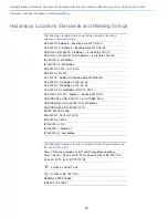
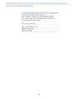
Страница 13: ...ng Strings The following hazardous locations marking strings are provided on the IW 6300H DC x K9 IW 6300H DCW x K9 Class I Division 2 Groups A B C and D Hazardous Locations Class I Zone 2 AEx ec IIC T4 Gc Zone 22 AEx tc IIIC T90 C Dc Ex ec IIC T4 Gc Ex tc IIIC T90 C Dc II 3G Ex ec IIC T4 Gc II 3D Ex tc IIIC T90 C Dc DEMKO 19 ATEX 2296X IECEx UL 19 0108X ...

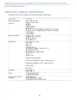
Страница 14: ... AC x K9 only VCCI CLASS A AS NZ CISPR32 WW EMC Immunity CISPR24 2010 A1 2015 EN 55024 2010 A1 2015 CISPR35 EN 55035 EN 300386 V1 6 1 Radio Wi Fi FCC Part 15 247 15 407 FCC 2 1091 RSS 247 RSS 102 AS NZS 4268 2017 MIC Article 2 paragraph 1 item 19 2 3 3 2 KCC Notice No 2013 1 EN 300 328 v2 1 1 v1 9 1 v1 8 1 EN 301 893 v2 1 1 v1 8 1 v1 7 1 EN 62311 LP0002 2018 Regulatory Domain Support FCC Americas ...

Страница 15: ...nd if not installed and used in accordance with the instructions may cause harmful interference However there is no guarantee that interference will not occur If this equipment does cause interference to radio or television reception which can be determined by turning the equipment off and on the user is encouraged to correct the interference by one of the following measures Reorient or relocate t...

Страница 16: ...nce for antennas that have 8 dBi to 14 dBi gain is 23 6 inches 60 cm from general bystanders The minimum separation distance from antennas that have less than 8 dBi gain to general bystanders is 9 8 inches 25 cm La distance minimale de séparation de l antenne de toute personne est de 9 8 25 cm pour les gains d antenne jusqu à 8 dBi et 23 6 60 cm pour les gains d antenne de 14 dbi pour assurer le r...

Страница 17: ...MC requirements of the Medical Devices Directive 93 42 EEC NOTE This equipment is intended to be used in all EU and EFTA countries Outdoor use may be restricted to certain frequencies and or may require a license for operation For more details contact Cisco Corporate Compliance The product carries the CE Mark Declaration of Conformity for RF Exposure This section contains information on compliance...

Страница 18: ...nsmitter and receiver It is designed not to exceed the limits for exposure to radio waves radio frequency electromagnetic fields as referenced in FCC Part 1 1310 The guidelines are based on IEEE ANSI C 95 1 92 and include a substantial safety margin designed to ensure the safety of all persons regardless of age and health As such the systems are designed to be operated as to avoid contact with the...

Страница 19: ...out Biological Effects and Potential Hazards of Radio Frequency Electromagnetic Fields FCC Bulletin 65 Evaluating Compliance with the FCC guidelines for Human Exposure to Radio Frequency Electromagnetic Fields FCC Bulletin 65C 01 01 Evaluating Compliance with the FCC guidelines for Human Exposure to Radio Frequency Electromagnetic Fields Additional Information for Evaluating Compliance for Mobile ...

Страница 20: ...526 4000 800 553 NETS 6387 Fax 408 527 0883 Cisco and the Cisco logo are trademarks or registered trademarks of Cisco and or its affiliates in the U S and other countries To view a list of Cisco trademarks go to this URL www cisco com go trademarks Third party trademarks mentioned are the property of their respective owners The use of the word partner does not imply a partnership relationship betw...

Отзывы: