


Chapter 2 Installation
Where to Go Next
2-34
Catalyst 2900 Series XL Hardware Installation Guide
78-6461-03
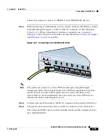
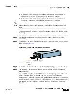
Step 3
Using the supplied rollover cable, connect one end of the rollover cable into the
console port, as shown in
Figure 2-20
. See the
“Identifying a Rollover Cable”
section on page B-6
for a description of the pinout.
Figure 2-20 Connecting to the Console Port
Step 4
Attach the supplied RJ-45-to-DB-9 female DTE adapter to a PC or attach an
appropriate adapter to the terminal.
Step 5
Connect the other end of the supplied rollover cable to the attached adapter.
Step 6
Start up the terminal-emulation program.
Where to Go Next
After the switch passes POST, it can operate on its default settings and passwords
after you configure IP information on the switch. For information about using the
setup program, refer to the Release Notes for the Catalyst 2900 Series XL and
Catalyst 3500 Series XL Cisco IOS Release 12.0(5)WC(1).
For information about configuring the switch, refer to the Catalyst 2900 Series XL
and Catalyst 3500 Series XL Software Configuration Guide.
47
308
DC INPUTS FOR REMO
TE
POWER SUPPL
Y
SPECIFIED IN MANU
AL.
+5V @24A, +12V @1.0A
Console port
Rollover cable
CONSOLE
Содержание Catalyst 2900 Series XL
Страница 4: ......
Страница 10: ...Contents x Catalyst 2900 Series XL Hardware Installation Guide 78 6461 03 ...
Страница 88: ...Appendix A Technical Specifications A 6 Catalyst 2900 Series XL Hardware Installation Guide 78 6461 03 ...
Страница 138: ...Index IN 8 Catalyst 2900 Series XL Hardware Installation Guide 78 6461 03 ...


