background image


6-3

Cisco 3200 Series Router Hardware Reference

OL-5816-10

Chapter 6      Wireless Mobile Interface Cards

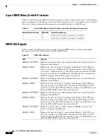
In contrast, the Serial Mobile Interface Card (SMIC) and FESMIC communicate with the router through 
the PC/104-

Plus

 bus. The interfaces are configured through the router console port, and all of the router 

and FESMIC Fast Ethernet ports are identified by using the slot/port format.

The WMIC runs an independent Cisco IOS image and when it is configured, the link between the WMIC 
and the router forms an internal LAN. In standard configurations, a WMIC Fast Ethernet port is never 
brought out to the end cap.

The WMIC console port is brought out to the corresponding RJ-45 port on the I/O end cap, replacing a 
Fast Ethernet port. If the router includes one WMIC, the RS-232 WMIC console port replaces a Fast 
Ethernet port on the end cap. If the router includes two WMICs, two WMIC EIA/TIA-232 console ports 
replace two Fast Ethernet ports on the end cap. 

Note

At present, even if the router contains zero WMICs, in standard configurations a maximum of three Fast 
Ethernet ports are brought out to the end cap. Unused EIA/TIA-232 ports are sealed.

Fast Ethernet Signals on the WMIC

The Fast Ethernet signals are delivered through a 10-pin header. LED signals and EIA/TIA-232 console 
signals are provided through the 24-pin multifunction header. 

There is one set of fixed Fast Ethernet signals on the WMIC. The Fast Ethernet port signals comply with 
IEEE 802.3. The signals are provided through the Ethernet headers, which support the following:

Autonegotiation for 10/100BASE-TX connection

Full-duplex and half-duplex modes 

Low-power sleep mode

10BASE-T and 100BASE-TX using a single Ethernet connection

Robust baseline wander correction performance 

Standard carrier signal multiple access collision detect (CSMA/CD) or full-duplex operation 

Integrated LED drivers

Note

If Auto-MDIX is disabled, when connecting to Ethernet switches or repeaters, use a straight-through 
cable. When connecting to compatible workstations, servers, and routers, use a crossover cable. If 
Auto-MDIX is enabled, you can use either a straight-through cable or a crossover cable to make the 
connection, as the router automatically changes the signals on the pins to compensate.

Содержание C3230-1W-49-K9 - 3230 WMIC Card Bundle Router

Страница 1: ...Cisco Systems Inc 170 West Tasman Drive San Jose CA 95134 1706 USA http www cisco com Tel 408 526 4000 800 553 NETS 6387 Fax 408 527 0883 Cisco 3200 Series Router Hardware Reference February 2008 Text Part Number OL 5816 10 ...

Страница 2: ...ops Move the equipment to one side or the other of the television or radio Move the equipment farther away from the television or radio Plug the equipment into an outlet that is on a different circuit from the television or radio That is make certain the equipment and the television or radio are on circuits controlled by different circuit breakers or fuses Modifications to this product not authori...

Страница 3: ...hernet and WMIC Console Ports 1 8 Cisco 3270 Router I O End Cap 1 9 Cisco 3230 Router I O End Cap 1 12 Protective End Cap Cover 1 13 I O End Cap Port Signals 1 15 Gigabit Ethernet Signal Limitations 1 15 Fast Ethernet Signals 1 15 Fast Ethernet Port Cabling for the Cisco 3250 and Cisco 3230 Routers 1 16 Console Port Signals 1 17 AUX Port Signals 1 17 Cisco 3200 Rugged Enclosure LED Indications 1 1...

Страница 4: ... Signals on the MARC 3 3 Console and Auxiliary Signals 3 4 C H A P T E R 4 Fast Ethernet Switch Mobile Interface Card 4 1 Autonegotiation and Auto MDI MDIX 4 2 MAC Address Allocation 4 2 FESMIC Component Systems 4 3 Signals for the FESMIC 4 4 FESMIC Rotary Switch Positions 4 5 C H A P T E R 5 Serial Mobile Interface Card 5 1 SMIC Component Systems 5 2 Signals for the SMIC 5 3 4 Port SMIC Rotary Sw...

Страница 5: ...l Workgroup Bridge Limitations 6 12 4 9 GHz Public Safety WMIC Features 6 13 4 9 GHz Channels 6 13 Throughput 6 14 Modulation 6 14 Receive Sensitivity 6 15 5 0 GHz 802 11h Radio Features 6 15 5 0 GHz 802 11h Channels 6 15 Throughput 6 16 Modulation 6 16 Receive Sensitivity 6 16 Transmit Sensitivity 6 17 Related Documentation 6 17 Replacing SFP Modules into SFP Module Slots B 2 Diagnosing SFP Probl...

Страница 6: ...Contents vi Cisco 3200 Series Router Hardware Reference OL 5816 10 ...

Страница 7: ...a particular environment Custom solutions based on Cisco cards must include a power source cables and an enclosure For information about the specific hardware configuration of your router contact your SI The following chapters provide information that you need for understanding the physical components of a completed Cisco 3200 Series router This document is not intended to cover assembly or repair...

Страница 8: ...evices can be assigned and how the role of a device affects its ability to associate or not associate with other wireless devices Cisco 3200 Series Wireless MIC Software Configuration Guide OL 6415 05 Provides sample procedures for using the IOS commands to configure Wireless Mobile Interface Cards WMICs Cisco 3200 Series Mobile Access Router Software Configuration Guide OL 1926 06 Provides sample...

Страница 9: ...ww cisco com en US docs general whatsnew whatsnew html Subscribe to the What s New in Cisco Product Documentation as a Really Simple Syndication RSS feed and set content to be delivered directly to your desktop using a reader application The RSS feeds are a free service and Cisco currently supports RSS version 2 0 Conventions This publication uses these conventions to convey instructions and infor...

Страница 10: ...schriften raadplegen Varoitus Tämä varoitusmerkki merkitsee vaaraa Olet tilanteessa joka voi johtaa ruumiinvammaan Ennen kuin työskentelet minkään laitteiston parissa ota selvää sähkökytkentöihin liittyvistä vaaroista ja tavanomaisista onnettomuuksien ehkäisykeinoista Tässä julkaisussa esiintyvien varoitusten käännökset löydät liitteestä Translated Safety Warnings käännetyt turvallisuutta koskevat...

Страница 11: ...go Encontra se numa situação que lhe poderá causar danos fisicos Antes de começar a trabalhar com qualquer equipamento familiarize se com os perigos relacionados com circuitos eléctricos e com quaisquer práticas comuns que possam prevenir possíveis acidentes Para ver as traduções dos avisos que constam desta publicação consulte o apêndice Translated Safety Warnings Traduções dos Avisos de Seguranç...

Страница 12: ...xii Cisco 3200 Series Router Hardware Reference OL 5816 10 ...

Страница 13: ...rackets so that the unit can be mounted upside down if required A design that meets NEMA4 requirements impervious to rain or hose directed water The enclosure is slightly rounded on the top and bottom This provides a non pooling surface in case the enclosure is exposed to water Maximum heat dissipation Thermally conductive pads and thermal vias around the board perimeter of each card physically co...

Страница 14: ... the longer Cisco 3270 Rugged Enclosure is similar Figure 1 1 Exploded View of a Rugged Enclosure The enclosures are sealed by using O rings between the extrusion and the end caps 1 I O end cap1 1 This end cap shows four serial ports but the typical configuration has two serial ports 2 Wiring card 3 Card stack 4 Extrusion body of the enclosure 5 Antenna end cap 1 2 3 4 5 270439 ...

Страница 15: ...all ports are copper If the Cisco 3270 Router includes a fiber optic port it operates at a temperature range from 40 to 147 F 40 to 64 C The Cisco 3270 Rugged Enclosure is designed to meet NEMA4 requirements Figure 1 2 shows an example of a fully assembled Cisco 3270 Rugged Enclosure Note the greater length to accommodate the Cisco 3270 Rugged Router card and future expansion Figure 1 2 Cisco 3270...

Страница 16: ... A base configuration includes one of each of the following Cisco 3270 Rugged Router card SMIC FESMIC and MRPC In the Cisco 3270 Rugged Enclosure the cards should be stacked in the order shown in Figure 1 3 The figure includes three optional WMICs If WMICs are added the first WMIC should be installed on the bottom of the stack and the next two WMICs should be installed at the top of the stack Figu...

Страница 17: ...r Card MARC This enclosure operates in a temperature range from 40 to 165 F 40 to 74 C and is certified to meet NEMA4 requirements Figure 1 4 shows an example of a Cisco 3230 Rugged Enclosure Figure 1 4 Cisco 3230 Rugged Enclosure 1 Front of the enclosure I O end cap 1 1 This end cap shows four serial ports but the typical configuration has two serial ports 2 Back of the enclosure antenna end cap ...

Страница 18: ...RC Up to three WMICs One SMIC or no SMIC One FESMIC One MRPC A basic configuration includes one of each of the following MARC SMIC FESMIC WMIC and MRPC In the Cisco 3230 Rugged Enclosure the cards should be stacked in the order shown in Figure 1 5 The two optional WMICs are on the top of the stack Figure 1 5 Cisco 3230 Router Stack 1 WMIC 1 2 MRPC 3 MARC 4 SMIC 5 FESMIC 6 WMIC 2 7 WMIC 3 270443 7 ...

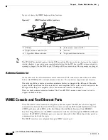
Страница 19: ...nd using the protective port covers provided on ports that are not in use and using port covers provided on the mating cables Antenna End Cap The antenna end cap has four antenna ports on the flat side and two ports on the top surface The end cap is used with the Cisco 3270 Rugged Enclosure or the Cisco 3230 Rugged Enclosure The antenna ports are connector type RP TNC Each RP TNC is connected inte...

Страница 20: ...rts on the FESMIC to provide a communications link with the router In contrast the Serial Mobile Interface Card SMIC and FESMIC communicate with the router through the bus All the router Fast Ethernet ports are addressed by using the slot port format In typical configurations the first WMIC Fast Ethernet port is connected to the routed Fast Ethernet port on the router card The Fast Ethernet ports ...

Страница 21: ...e router RJ 45 ports 8 and 9 are labeled WMIC 1 and WMIC 2 Port 10 is labeled FE1X 1 Router console port 2 FE0 port 3 FE1 port 4 FE0X port 5 GE0 Gigabit Ethernet port 6 Fiber Optic port shown or Copper Gigabit Ethernet GE1 port 7 USB0 bottom and USB1 top ports 8 Ser2 Smart Serial port 9 Power input 10 Ser1 EIA TIA 232 DCE port 11 AUX port 12 Ser0 EIA TIA 232 DCE port 13 FE1X port or WMIC 3 console...

Страница 22: ...67 integrity The part numbers for the connectors are Tyco 1828618 1 and Tyco 1828618 2 Caution When connecting fiber optic cables observe all standard procedures for safety and maintain a clean connection Power Connector IP 67 Integrity To seal the Tyco DC Power input power connector and maintain IP 67 integrity use the following parts 796094 2 CPC housing 66101 3 contact 207489 1 boot 207490 1 ca...

Страница 23: ...sh Ready test time over 4 seconds If an unsupported USB flash storage device is plugged into a USB port an error might occur CSCsd44152 The error message is Failed to enumerate a USB device as not able to read the device s description To correct the problems remove any unsupported USB flash storage device and use only one supported device in one of the two USB ports The Cisco supported flash stora...

Страница 24: ...ith captive dust covers not shown that seal the ports and protect the pins The dust covers should be used to seal the ports when the ports are not otherwise covered by cable connectors 1 WMIC 1 console port 2 WMIC 2 console port 3 WMIC 3 console port 4 FE0 port 5 FE1X port 6 FE2X or MARC FE0X port for more information see the Fast Ethernet Port Cabling for the Cisco 3250 and Cisco 3230 Routers sec...

Страница 25: ...The protective end cap cover also provides added protection for in vehicle use inhibiting corrosion on the ports and potential damage from objects that are stored near the enclosure inside a vehicle The protective end cap cover has a ruggedized design for high reliability and NEMA4 compliance Figure 1 9 Cisco 3200 Rugged Enclosure Protective End Cap Cover 1 Hinge point 2 NEC cable pass through 3 H...

Страница 26: ...ened bolts on the right side of the end cap cover to between 58 and 68 in lb Step 4 Ensure that the gasket is fully seated in the protective end cap cover Step 5 Close the cover on the protective end cap cover and ensure that it is fully seated Step 6 Re torque the end cap cover bolts on left side of the end cap cover to between 58 and 68 in lb Step 7 Tighten the 8 32 protective cover screws 18 in...

Страница 27: ...uns might cause CRC errors on the peer router Fast Ethernet Signals A Cisco router identifies a Ethernet port interfaces by slot number and port number in the format of slot port For example the slot port address of a Fast Ethernet interface on the Cisco 3230 Rugged Enclosure is 0 0 The Cisco 3270 Router Ethernet port signals are in compliance with IEEE 802 3 The interfaces support the following A...

Страница 28: ...C FE0X port does not support autodetection To connect a port marked MARC FE0X to a routing Ethernet port that does not support autodetection use a straight through Ethernet cable To connect a MARC FE0X port to a hub switch a router hub or switch port use a crossover Ethernet cable Table 1 1 shows the connections For example a port marked FE0X requires a crossover Ethernet cable to establish the Et...

Страница 29: ...ll modem control of DTR DSR RTS and CTS signals AUX Port Signals The AUX port is a serial asynchronous port that supports the following speeds Cisco 3270 Rugged Router card in the Cisco 3270 Router 1 2 kbps 2 4 kbps 4 8 kbps 9 6 kbps 19 2 kbps 38 4 kbps 57 6 kbps 115 2 kbps and 460 kbps Mobile Access Router Card MARC in the Cisco 3230 Router 1 2 kbps 2 4 kbps 4 8 kbps 9 6 kbps 19 2 kbps 38 4 kbps ...

Страница 30: ...er card Solid green OK Blinking Booting and self testing Black Not OK or the power is off Serial Status Link 1 status link LED per serial port Solid green Link OK Black No link is detected Amber blink Activity Fast Ethernet 1 LED per port except for the fiber optic port which has no LEDs Link LED Solid green Link OK Black No link is detected Activity LED Black No activity and no connection Green b...

Страница 31: ... green OK Blinking Booting and self testing Black Not OK or the power is off Serial Status Link 1 status link LED per serial port Solid green Link OK Black No link is detected Amber blink Activity Fast Ethernet 2 LEDs per Fast Ethernet port Link LED Solid green Link OK Black No link is detected Activity LED Black No activity Green blink Activity WMIC Console Installation or Operation Mode For inst...

Страница 32: ...a card with thermal plates The conduction cooling removes the need for internal fans Figure 1 11 Router Card with Thermal Plates Table 1 5 WMIC Operational Mode Indication Status LED Radio LED Green steady At least one bridge is associated Red steady Loading firmware Firmware failure Green blink No bridges are associated Transmitting or receiving packets on the radio port Amber blink General warni...

Страница 33: ... The bolts for the notches in the mounting bracket can be installed on the enclosure before the other bolts are installed The partially installed bolts provide enough support to allow you to install the router in the bracket and then install and tighten the remaining bolts The torque values for the mounting bracket screws are from 58 to 68 in lb Figure 1 12 shows the Cisco 3270 Rugged Enclosure mo...

Страница 34: ...es Figure 1 13 shows the dimensions of the Cisco 3270 Rugged Enclosure mounting bracket Figure 1 13 Cisco 3270 Rugged Enclosure Mounting Bracket Dimensions Figure 1 14 shows the Cisco 3230 Rugged Enclosure mounting bracket Figure 1 14 Cisco 3230 Rugged Enclosure Mounting Bracket 3 9 232600 127452 ...

Страница 35: ...r Hardware Reference OL 5816 10 Chapter 1 Cisco 3200 Rugged Enclosures Figure 1 15 shows the dimensions of the Cisco 3230 Rugged Enclosure mounting bracket Figure 1 15 Cisco 3230 Rugged Enclosure Mounting Bracket Dimensions 232599 ...

Страница 36: ...1 24 Cisco 3200 Series Router Hardware Reference OL 5816 10 Chapter 1 Cisco 3200 Rugged Enclosures ...

Страница 37: ...5 MHz 256 MB 64 bit unbuffered double data rate DDR synchronous DRAM 64 MB 16 bit flash memory Two Fast Ethernet ports with autonegotiation Two Gigabit Ethernet port signal sets with autonegotiation the router can be ordered with support for one fiber optic port and one copper port or with two copper ports Console port signals with modem flow control Asynchronous EIA ITA 232 serial port signals wi...

Страница 38: ...nts see the Cisco 3200 Series Mobile Access Router Technical Reference OL 1927 Cisco 3270 Rugged Router Card Component Systems The industry standard architecture ISA buses and peripheral component interconnect PCI buses on the Cisco 3200 Series Mobile Access Router cards provide power to the components on the cards Both buses comply with the PC 104 Plus standard The ISA bus allows PC 104 Plus ISA ...

Страница 39: ...odule installation On the PCI bus pin D30 is removed and the D30 opening is plugged On the ISA bus pin C19 and pin B10 are removed and the C19 and B10 openings are plugged 1 Gigabit Ethernet 1 fiber optic or copper 2 Gigabit Ethernet 0 3 Fast Ethernet 1 4 Fast Ethernet 0 5 USB ports and USB LEDs 6 PCI bus for future expansion 7 ISA bus 8 Jumper for optional Fast Ethernet 01 1 Factory set Do not mo...

Страница 40: ...ayer Security TLS Secure Real time Transport Protocol SRTP 802 11i Internet SCSI iSCSI and Internet key exchange IKE processing The security engine contains four crypto channels a controller and a set of crypto execution units EUs The SEC can act as a master on the internal bus This allows the SEC to alleviate the data movement bottleneck normally associated with slave only cores The host processo...

Страница 41: ...e digest Hash based Message Authentication Code HMAC with either algorithm Random Number Generator RNG Four crypto channels each supporting multi command descriptor chains Static or dynamic assignment of crypto execution units through an integrated controller Buffer size of 256 bytes for each EU with flow control for large data sizes Caution Zeroization is a feature that erases all potentially sen...

Страница 42: ...Note Changing the Ethernet port speed and duplex mode configuration might shut down and reenable the interface during the reconfiguration The procedure to set the port speed for a copper Gigabit Ethernet port is as follows To set the mode on a copper Gigabit Ethernet port to duplex Note The Gigabit Ethernet optical fiber interface only supports full duplex mode a Cisco IOS command to set the mode ...

Страница 43: ...for the security engine that define the cryptographic function to be performed and the location of the data The security engine bus mastering capability permits the host processor to set up a crypto channel with a few short register writes leaving the security engine to perform reads and writes on system memory Security Engine Features The execution units are Public Key Execution Unit PKEU support...

Страница 44: ...ow 40ºC or exceeds 95ºC until the temperature falls back to its normal range Note The signal and LED are available only on the Cisco 3270 Rugged Router card not on the Cisco 3200 rugged enclosures Cisco 3270 Rugged Router Card MAC Address Allocation Cisco 3270 Rugged Router card equipped routers are allocated 37 MAC addresses starting from the base MAC address A card equipped Cisco 3270 Rugged Rou...

Страница 45: ... autonegotiation Console connection with hardware software flow control Asynchronous EIA TIA 232 serial connection with a 5 V auxiliary power supply for Global Positioning System GPS and auxiliary AUX devices The AUX port speed can be configured as 2400 4800 9600 19200 38400 57600 or 115200 bps Use the line aux linenumber speed command to modify the speed of the port A 32 bit PCI bus version 2 1 r...

Страница 46: ...wer to the components on the cards Both buses comply with the PC 104 Plus standard The ISA bus allows PC 104 Plus ISA signals to pass through the card bus but the Cisco cards do not use any of the signals Caution If you add non Cisco cards that generates signal on the PCI bus the router might shut down Please do not add non Cisco cards that generate signals on the PCI bus Figure 3 1 shows the MARC...

Страница 47: ...router identifies a Fast Ethernet interface address by its slot number and port number in the format slot port The slot port address of a Fast Ethernet interface on the MARC is 0 0 The Fast Ethernet port signals are in compliance with IEEE 802 3 They are provided through the 10 pin Ethernet header which supports the following Autonegotiation and parallel detection MII interface with extended regis...

Страница 48: ...ial DCE 1 2 kbps 2 4 kbps 4 8 kbps 9 6 kbps 19 2 kbps 38 4 kbps 57 6 kbps and 115 2 kbps baud rates Support full modem control DTR DSR RTS and CTS signals The AUX port is a serial asynchronous port that works at speeds of 1 2 kbps 2 4 kbps 4 8 kbps 9 6 kbps 19 2 kbps 38 4 kbps 57 6 kbps and 115 2 kbps The AUX port supports the following Asynchronous serial DTE Baud rates range from 1 200 to 115 00...

Страница 49: ...rt for 802 1D standard bridging 802 1Q trunking and 802 1P class of service CoS Layer 3 routing support between VLANs Only one FESMIC is supported in a Cisco 3200 Series router Additional cards and components provide power and link interfaces to the FESMIC The exact configuration of your router will vary depending on how your vendor configured it Note This section provides basic information about ...

Страница 50: ...autonegotiation enabled the current software does not implement an explicit command line interface CLI command to allow you to disable Auto MDIX during autonegotiation Autonegotiation Enable To enable autonegotiation use the following configuration Router config FastEthernet m n Router config if speed auto where m is the slot and n is the port number Autonegotiation Disable To disable autonegotiat...

Страница 51: ...ards do not use any of the signals The PCI bus signals allow the Cisco cards to communicate Non Cisco cards cannot communicate with the Cisco 3200 Series Mobile Access Router cards over the PCI bus Caution If you add non Cisco cards that generate signals on the PCI bus the router might shut down Do not add non Cisco cards that generate signals on the PCI bus Figure 4 1 shows the 2 port FESMIC head...

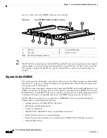
Страница 52: ...ort any ISA bus signals The PCI bus connector supports communication between the FESMIC the Serial Mobile Interface Card SMIC and the Cisco 3270 Rugged Router card or Mobile Access Router Card MARC The Wireless Mobile Interface Card WMIC communicates with the router through an internal Fast Ethernet port and is configured through an independent console port the WMIC draws power only from the bus T...

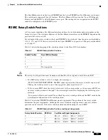
Страница 53: ...nique and should not be assigned to more than one MIC If a MIC rotary switch is set to 3 or higher the message is MIC 3 SLOTNOTSUPPORTED The MIC cannot operate when the rotary switch is in position 3 Change the switch position to one of the supported unused positions 0 2 If two or more MICs have the rotary switches set to the same position or if one or more MICs are in rotary switch positions 4 th...

Страница 54: ...4 6 Cisco 3200 Series Router Hardware Reference OL 5816 10 Chapter 4 Fast Ethernet Switch Mobile Interface Card ...

Страница 55: ...ink Control HDLC asynchronous synchronous and octet oriented PPP modes The signals can be configured to any serial standard EIA TIA 232 EIA TIA 449 EIA TIA 530 EIA TIA 530A EIA TIA X 21 or CCITT V 35 DCE and DTE mode support on each set of serial signals Speeds of 2 Mbps for synchronous data transfer and 115 kbps for asynchronous data transfer on each serial interface All serial standards reach 2 ...

Страница 56: ...f you add non Cisco cards that generate signals on the PCI bus the router might shut down Do not add non Cisco cards that generate signals on the PCI bus Figure 5 2 4 port SMIC Header and Bus Locations 1 PCI bus 2 60 pin multifunction header for Serial 0 and Serial 1 signals 3 ISA bus 4 Rotary switch 95227 1 3 2 4 1 PCI bus 2 60 pin multifunction header for Serial 2 and Serial 3 signals 3 ISA bus ...

Страница 57: ...al assignments The position of the rotary switch determines the port assignments Although the rotary switch has 8 positions only 1 of 4 positions can be selected The rotary switch position should be unique for each mobile interface card MIC card Table 5 1 4 port SMIC Rotary Switch Settings and Port Assignments Position MIC Slot Port Assignments 0 1 Serial 1 0 Serial 1 1 Serial 1 2 Serial 1 3 1 2 S...

Страница 58: ... DCD and clear to send CTS signals are detected The LED is on when a serial port is in DCE mode and when the data terminal ready DTR and request to send RTS signals are detected SERIAL1 ACTIVITY Blinks once when a packet is either transmitted from or received on Serial 1 Originates from Header 5 SERIAL1 LINK Indicates the status of Serial 1 Originates from Header 5 The LED is on when the serial po...

Страница 59: ...sumption The SMIC draws power from the PCI and the ISA connectors Table 5 6 shows the estimated power consumption Note that these are theoretical maximum wattages Table 5 6 SMIC Estimated Power Consumption Voltage Current Draw Power Source 5 0 V 1 0 A 5 0 W ISA and PCI connectors 3 3 V 0 5 A 1 7 W PCI connectors ...

Страница 60: ...5 6 Cisco 3200 Series Router Hardware Reference OL 5816 10 Chapter 5 Serial Mobile Interface Card ...

Страница 61: ...o meet the requirements specified under FCC Part 90 20 This chapter provides basic information about the WMIC hardware for performing simple troubleshooting such as reconnecting a loose cable To solve more difficult problems contact your vendor WMIC Component Systems The ISA buses and PCI buses on the Cisco 3200 Series router cards provide power to the components on the cards The WMIC does not rec...

Страница 62: ...antenna to the low noise amplifier LNA on the receiver and carries the RF signal from the power amplifier PA to the antenna that radiates the RF signal There are many antenna connector families The Cisco RP TNC antenna connector can be used to support standard antennas WMIC Console and Fast Ethernet Ports Cisco 3200 Series router cards do not support any ISA bus signals The PCI bus connector suppo...

Страница 63: ...configurations a maximum of three Fast Ethernet ports are brought out to the end cap Unused EIA TIA 232 ports are sealed Fast Ethernet Signals on the WMIC The Fast Ethernet signals are delivered through a 10 pin header LED signals and EIA TIA 232 console signals are provided through the 24 pin multifunction header There is one set of fixed Fast Ethernet signals on the WMIC The Fast Ethernet port s...

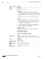
Страница 64: ...ure The indicator is off when the Ethernet cable is not connected Table 6 1 lists the details of LED indicator signals Table 6 1 Indicator Signals Message Type Ethernet Indicator Status Indicator Radio Indicator Meaning Boot loader status Green Green DRAM memory test Amber Red Board initialization test Blinking green Blinking green Flash memory test Amber Green Ethernet initialization test Green G...

Страница 65: ...disconnecting and reconnecting unit power Blinking red Hardware failure The wireless device must be replaced Firmware Upgrade Red Loading new firmware image Table 6 1 Indicator Signals continued Message Type Ethernet Indicator Status Indicator Radio Indicator Meaning Table 6 2 Key Features Feature Description Wireless Medium Direct Sequence Spread Spectrum DSSS Orthogonal Frequency Division Multip...

Страница 66: ...Message Authentication Code Protocol AES CCMP 128 bit key length Temporal Key Integrity Protocol TKIP WEP enhancements key hashing per packet keying message integrity check MIC and broadcast key rotation by using WPA TKIP All WMICs in Root Mode PEAP EAP TTLS LEAP EAP TLS EAP FAST and EAP SIM Cisco 3201 WMICs in Client Mode LEAP EAP TLS and EAP FAST Cisco 3202 and Cisco 3205 WMICs in Client Mode LE...

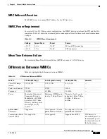
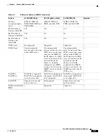
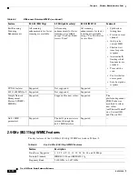
Страница 67: ...wer Source 5 0 V 0 4 A 2 0 W ISA and PCI connectors 3 3 V 1 7 A 5 6 W PCI connectors Table 6 4 Differences Between WMICs Feature 2 4 GHz 802 11b g 4 9 GHz public safety 5 0 GHz 802 11h Comment Cisco IOS image release 12 3 8 JK 12 3 2 JK 12 3 2 JL Cookie and banner C3201 C3202 C3205 Frequency 2 4 GHz 4 9 GHz 5 0 GHz Power Maximum Orthogonal Frequency Division Multiplexing OFDM power level is 15 dbm...

Страница 68: ... Access Point AP Work Group Bridge WGB Non Root Bridge NRB Root Bridge RB and Access Point AP World Mode Supported Supported only if the wireless device is in root access point or root bridge mode Not supported in client modes Supported only if the wireless device is in root access point or root bridge mode Not supported in client modes World mode on the client side updates a client with the chann...

Страница 69: ... and the IP address is statically configured on a WMIC acting as root device the WMIC can work with the WDS server Can automatically discover and work with a WDS server on the same subnet as the WMIC If the IP address of a WDS server is anywhere on the network and the IP address is statically configured on a WMIC acting as root device the WMIC can work with the WDS server EAP TLS EAP TTLS EAP TLS ...

Страница 70: ...ncies are scanned Time out the scan Use first better access point Save best probe response CCXv4 features Supported Not supported Supported 802 11e MMN QoS Supported Not supported Supported Simple Network Management Protocol SNMP MIB IDs Supported Supported for new values Supported The platform dependent SNMP code was modified to return new values entPhysicalVendorT ype System OID and Chassis ID D...

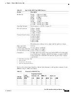
Страница 71: ...ximum power settings vary to comply with the regulatory domain Range typical at 100 mW transmit power setting with 6 dBi diversity dipole antenna Outdoor 0 5 mile 804 m at 45 Mbps 1 mile 1609 m at 11 Mbps 3 miles 4 827 m at 1 Mbps Compliance 2 4 GHz 802 11b g operates license free under FCC Part 15 and qualifies as a Class B device complies with DOC regulations complies with ETS 300 328 FTZ 2100 a...

Страница 72: ...idge mode so that the WMIC is manageable from the MAR through the Mobile IP tunnel from the infrastructure side If the dynamic Collocated Care of Address CCoA is used on the Cisco 3200 Series Wireless and Mobile Router you should configure the static IP address using the ip secondary address command The universal workgroup bridge is not compatible with the Tropos version 3 1 1 2 AP A universal wor...

Страница 73: ...resent there is no IEEE 4 9 GHz public safety standard however the public safety standard for the 4 9 GHz WMIC is similar to the IEEE 802 11a standard Frequency Band 4 940 GHz to 4 990 GHz Available Transmit Power Settings 50 mW 17 dBm 40 mW 16 dBm 30 mW 15 dBm 20 mW 13 dBm 10 mW 10 dBm 5 mW 7 dBm Compliance 4 9 GHz public safety Operation restricted to operators meeting requirements of CFR47 Part...

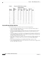
Страница 74: ...ge for a 20 MHz wide channel Modulation Table 6 9 lists the modulation supported modulations and data rates 35 4957 5 40 4960 0 4960 0 45 4962 5 50 4965 0 4965 0 55 4967 5 60 4970 0 4970 0 65 4972 5 70 4975 0 4975 0 75 4977 5 80 4980 0 4980 0 85 4982 5 90 4985 0 91 93 95 4987 5 97 99 Table 6 8 FCC 4 9 GHz Operational Channels as per the TIA TR 8 Specification continued Operating Channel Numbers Ch...

Страница 75: ...available as the Cisco 3205 WMIC supports the following channels and frequencies in the ETSI regulatory domain 5 250 GHz to 5 350 GHz 5260 MHz 52 5280 MHz 56 5300 MHz 60 5320 MHz 64 5 470 GHz to 5 725 GHz 5500 MHz 100 5520 MHz 104 5540 MHz 108 5560 MHz 112 5580 MHz 116 5600 MHz 120 5620 MHz 124 5640 MHz 128 5660 MHz 132 5680 MHz 136 5700 MHz 140 Channels 52 through 140 are ETSI outdoor channels 16...

Страница 76: ...e following are range performance estimations 6 Mbps at 10 kilometers 6 miles at 30 dBm equivalent isotropically radiated power EIRP 1 Mbps at 30 kilometers 18 miles at 30 dBm EIRP Modulation Table 6 11 lists the supported 5 0 GHz 802 11h modulations and data rates Receive Sensitivity Table 6 12 shows the receive sensitivity for 5 0 GHz 802 11h radios Table 6 11 5 0 GHz 802 11h Modulations and Dat...

Страница 77: ...o Internetwork Design Guide Click this link to browse to this document http www cisco com univercd cc td doc cisintwk idg4 index htm Cisco Internetworking Technology Handbook Click this link to browse to this document http www cisco com univercd cc td doc cisintwk ito_doc index htm Cisco Internetworking Troubleshooting Guide Click this link to browse to this document http www cisco com univercd cc...

Страница 78: ...6 18 Cisco 3200 Series Router Hardware Reference OL 5816 10 Chapter 6 Wireless Mobile Interface Cards ...

Страница 79: ...uld be used to seal the port We recommend 4 1 shrink ratio tubing one piece is provided To seal the Smart Serial ports complete the following steps Step 1 Cut a 1 8 inch length of heat shrink tubing Step 2 If the Smart Serial port cable is attached remove it Step 3 Feed the cable through the heat shrink tubing Step 4 Secure the cable back onto the Smart Serial port by using the jack screws of the ...

Страница 80: ...ix A Smart Serial Port External Seal Step 6 Position the heat shrink tubing as shown in Figure A 2 so that one end is over the cable molding over the chassis protrusion and abuts the end cap Figure A 2 Positioning the Heat Shrink Tubing Over the Cable Molding 270449 ...

Страница 81: ...by using a heat gun Heat the tubing until it is reduced in size and fits snugly over the chassis protrusion of the smart serial port Once it is secure direct the heat toward the other end of the tubing to shrink it against the cable molding as shown in Figure A 3 Figure A 3 Applying Heat to the Heat Shrink Tubing 270450 ...

Страница 82: ...A 4 Cisco 3200 Series Router Hardware Reference OL 5816 10 Appendix A Smart Serial Port External Seal ...

Страница 83: ...e cable and the cable must not exceed the stipulated cable length for reliable communications Figure B 1 shows an SFP module that has a bale clasp latch Caution We strongly recommend that you not install or remove the SFP module while the fiber optic cable is attached to it because of the potential damage to the cables to the cable connector or to the optical interfaces in the SFP module Disconnec...

Страница 84: ...ule to keep the optical interfaces clean Caution Do not touch the optical surfaces Step 5 Unlock and remove the SFP module Figure B 2 Disconnecting SFP Latch Mechanisms Step 6 Pull the bale clasp latch out and down to eject the module If the bale clasp latch is obstructed and you cannot use your index finger to open it use a small flat blade screwdriver or other long narrow instrument to open the ...

Страница 85: ...rs by using standard procedures Step 14 Insert the LC cable connector into the SFP module Step 15 Verify that the gasket is in place and replace the Antenna end cap by using a 3 8 in wrench to remove the bolts torquing the bolts to 58 to 68 inch pounds Diagnosing SFP Problems You can get statistics from the browser interface from the CLI or from an SNMP workstation Common SFP module problems fall ...

Страница 86: ...ule and replace it with a Cisco approved module Use the errdisable recovery cause gbic invalid global configuration command to verify the port status and enter a time interval to recover from the error disable state The port is placed in error disabled state after SFP is inserted Bad or non Cisco approved SFP module Remove the SFP module from the switch and replace it with a Cisco approved module ...

Страница 87: ... Error Message UNSUPPORTED TRANCEIVER Unsupported SFP transceiver found on board Warranty support may void Explanation The transceiver module for the interface specified in the error message is not a Cisco supported module As a result of the error the module is disabled When Cisco determines that a fault or defect can be traced to the use of third party transceivers installed by a customer or rese...

Страница 88: ...B 6 Cisco 3200 Series Router Hardware Reference OL 5816 10 Appendix B SFP Module Replacement ...

Страница 89: ... GPS 3 1 audience viii auto detection 1 16 Auto MDIX 4 1 4 2 6 3 auto negotiation 3 1 4 2 6 3 AUX port enclosure 1 17 MARC 3 4 speed 2 4 Zeroization 2 5 3 1 B bridge packet data unit BPDU 4 2 bridging 4 1 broadcast key rotation 6 6 bus communication 2 2 4 3 5 1 6 1 bus keying feature 2 3 3 2 4 4 5 1 6 2 C card stack Cisco 3230 1 6 Cisco 3270 1 4 CCITT V 35 5 1 CCXv4 6 10 channel 2 4 GHz center fre...

Страница 90: ... TIA 449 5 1 EIA TIA 530 5 1 EIA TIA 530A 5 1 EIA TIA X 21 5 1 enclosure interface cards 1 1 mounting 1 1 encryption 6 5 end cap antenna 1 7 Cisco 3230 router I O 1 12 Cisco 3270 router I O 1 9 protective cover 1 13 errdisable recovery command B 4 error SFP module B 4 USB Flash storage device 1 11 Execution Units EUs 2 4 F Fast Ethernet auto negotiation 4 2 Cisco 3270 Rugged Router card 2 3 Cisco ...

Страница 91: ...d security engine 2 4 interface identification serial Cisco SMIC 5 4 interfaces AUX 1 17 2 4 3 4 console port 1 17 2 3 3 4 Fast Ethernet Cisco 3270 Rugged Router card 2 3 Cisco FESMIC 4 4 4 5 Cisco MARC 3 3 Cisco WMIC 6 3 end cap 1 15 serial Cisco 3270 Rugged Router card 2 1 Cisco MARC 3 1 Cisco SMIC 5 3 5 4 inter VLAN routing 4 2 IP 67 integrity 1 10 IPSec 2 7 ISA bus signals 2 2 3 2 4 3 6 1 iSCS...

Страница 92: ...s 6 8 N NEMA4 design 1 1 protective end cap cover 1 13 rugged enclosure Cisco 3230 1 5 Cisco 3270 1 3 non Cisco cards bus communication 2 2 4 3 5 1 6 1 O operational mode 1 19 WMIC LEDs 1 19 over temp LED 2 8 P PC 104 Plus 2 2 3 2 PCI bus 2 2 3 1 4 3 6 1 PEAP 6 6 performance problems solving B 3 per VLAN spanning tree PVST 4 2 ports 6 2 AUX 1 17 3 4 console 1 17 3 4 Fast Ethernet 2 1 3 1 4 1 seria...

Страница 93: ...lasp latch B 2 qualified parts B 1 replacement B 2 to B 3 replacement instructions B 1 show controller command 1 15 show interface d0 dfs command 6 16 signals Cisco FESMIC 4 4 Cisco MARC 3 3 Cisco SMIC 5 3 Fast Ethernet 3 3 4 1 6 2 ISA bus 2 2 3 2 4 3 6 1 PCI bus 2 2 3 1 4 3 6 1 serial 3 3 5 3 signal strength installation mode 1 19 sleep mode 6 3 smart serial port seal A 1 system integrity 1 10 SN...

Страница 94: ...torage device caveat 1 11 errors 1 11 V VLAN routing 4 2 W WDS server 6 9 Wedge Lok 1 20 WEP 6 6 wiring card 1 2 WMIC 2 4 GHz 802 11b g 6 1 4 9 GHz public safety 6 1 5 0 GHz public safety 6 1 console ports 1 9 mode installation and operation 1 19 order of installation 1 4 Z Zeroization AUX port 2 5 3 1 GPIO pin 2 5 ...

Отзывы: