Installation and Configuration
Mounting the Access Points
8
AP1010 Cisco Aironet 1000 Series IEEE 802.11a/b/g Lightweight Access Points with Internal
7817146-01
Note
If the screws do not securely hold the ceiling-mount base, remove the AP and adjust the screws until they
hold the ceiling-mount base securely.
4.
Attach the cables to the sides of the AP.
Note
When the AP is powered up and is associated with a Cisco Wireless LAN Controller (Green/Power and
Yellow/802.11b/g and/or Yellow or Amber/802.11a LEDs lit), the AP is broadcasting its beacon
signal(s). When this happens, complete the installation as quickly as possible to remove yourself from
within 8 inches (20 cm) of the AP to comply with FCC RF radiation exposure guidelines.
5.
Slide the ceiling-mount base onto the drywall, sheet metal, or other screw heads until it fits snugly
in place.
You have installed the AP . Repeat “
Mounting the Access Points
”
for each AP location, and then continue
with “
Returning MAC Information
”
.
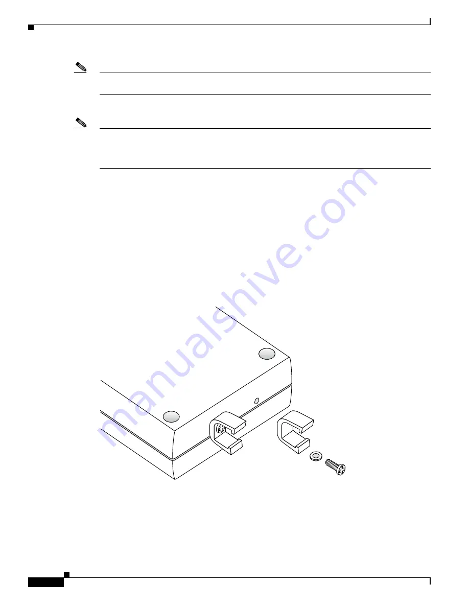
Ceiling-Mount Clips
When you are mounting the AP on the extruded aluminium rails of a hanging ceiling, use the
ceiling-mount clips to mount the AP as shown in the following figure and as described below:
Figure 5
Assembling the AP and Ceiling-Mount Clips
1.
Copy the MAC address(es) from the label(s) on the AP onto the corresponding location on the map.
MAC addresses have the format 00xxxxxxxxxx.
2.
Attach the ceiling-mount clips to the bottom of the AP using the factory-supplied machine screws
and washers.
3.
Snap the ceiling-mount clips onto a hanging ceiling rail.
135665


