Chapter 2 Installation
Installing the CPE On a Wall
2-10
Cisco 575 LRE CPE Hardware Installation Guide
78-11469-01
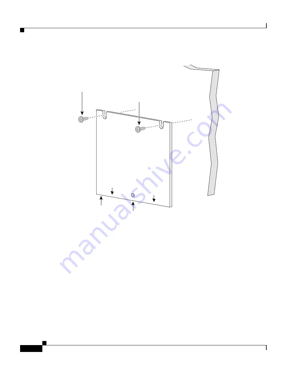
Figure 2-3
Installing the Mounting Screws On a Wall
Step 3
Peel the adhesive strip off the bottom of the screw template.
Step 4
Attach the screw template to the wall.
Step 5
Use a 1/44-inch bit to drill a 1/2-inch-deep hole in the two screw template slots.
Step 6
(Optional) If you wish to attach the cable lock after the cables are installed, drill
a 1/2-inch-deep hole in the screw template hole. For more information, see the
“Attaching the Cable Lock” section on page 2-16
.
Step 7
Insert two screws in the slots on the screw template, and tighten until they touch
the top of the screw template.
Step 8
Remove the screw template from the wall.
Step 9
Slide the CPE onto the screws until it locks in place. (See
Figure 2-4
.)
SCREW TEMPLA
TE
P/N 700-09589-01
THIS SIDE A
WAY FR
OM
MOUNTING SURF
AC
E
CABLE ENTR
Y
SIDE
Screw
Screw
Screw
template
Cable
lock hole
47503
CABLE ENTR
Y
SIDE
Содержание 575 LRE CPE
Страница 4: ......
Страница 8: ...Contents viii Cisco 575 LRE CPE Hardware Installation Guide 78 11469 01 ...
Страница 24: ...Chapter 1 Overview Rear Panel Description 1 6 Cisco 575 LRE CPE Hardware Installation Guide 78 11469 01 ...
Страница 44: ...Chapter 2 Installation Where to Go Next 2 20 Cisco 575 LRE CPE Hardware Installation Guide 78 11469 01 ...
Страница 48: ...Chapter 3 Troubleshooting 3 4 Cisco 575 LRE CPE Hardware Installation Guide 78 11469 01 ...


