8
2
Connect Cables (continued)
SEE MANUAL BEFORE INSTALLATION
SERIAL 1
SERIAL 0
CONN
CONN
WIC
2A/S
SEE MANUAL BEFORE INSTALLATION
SERIAL 1
SERIAL 0
CONN
CONN
WIC
2T
AUX
CONSOLE
ETHERNET 0 ACT
LINK
100-240V– 1A
50/60 Hz 47 W
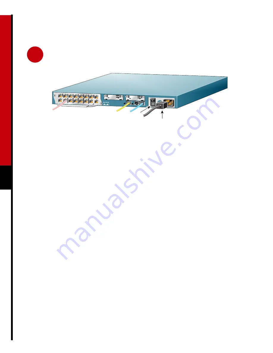
Power outlet
Power switch
MODEMS
EN
IN USE
IN USE
16AM
15
14
13
12
11
10
9
8
7
6
5
4
3
2
1
0
Connect Power and
Turn On the Router
1
Connect one end of the black power cord to the
power connector on the router’s rear panel.
2
Connect the other end of the power cord to an
electrical outlet.
3
Turn ON the power switch on the rear panel.
The green Power LED on the router’s front panel
blinks, as the router initializes, then stays on
when fully initialized. (It might take a moment
before this light goes on.)
4
Perform a quick visual inspection to ensure the
following:
— The router is plugged in, the power is turned
on, and the Power LED on the front panel
displays a solid green light. (If not, you
cannot install the Cisco Fast Step software.)
— The link LED (labeled LNK) next to the
Ethernet port, displays a solid green light. (If
this is not a solid light, check your cabling.)
— Each modem port you are currently setting
up has a pink modem cable connected to it.
— Each pink modem cable connected to a
modem port is also connected to an RJ-11
telephone wall jack or outlet.
You are now finished cabling the router and one or
more modems. The next section explains how to run
Cisco Fast Step software so you can use the router in
your network.


