
22-7
Cisco 10000 Series Router Quality of Service Configuration Guide
OL-7433-09
Chapter 22 Hierarchical Scheduling and Queuing
MQC Hierarchical Queuing with 3-Level Scheduler
Priority Service and Latency
The 3-level scheduler supports two levels of priority queues; for example, level 1 for voice traffic and
level 2 for video traffic.
For a priority class with policing configured, the 3-level scheduler always polices the priority traffic to
the rate specified in the
police
command (1000 kbps as shown in the following sample configuration),
regardless of whether or not the underlying interface is congested.
Router(config-pmap-c)#
police 1000
Router(config-pmap-c)#
priority
Note
The 3-level scheduler does not support the
priority
kbps
command.
Latency Requirements
Delay-sensitive traffic incurs a maximum of 10 milliseconds (ms) of latency on edge router interfaces
and a maximum of 1 ms of latency on core router interfaces. For interface speeds at T1/E1 and below,
the 3-level scheduler services 2 maximum transmission units (MTUs) of nonpriority traffic before
servicing a priority packet. Requirements for high-speed interfaces are not as strict as 2 MTUs, but are
always bound by 10 ms on edge interfaces and 1 ms on core interfaces.
The 3-level scheduler also supports the minimal latency requirement (2 MTUs of nonpriority traffic in
front of priority traffic) at the physical link rate. However, in some cases, it is impossible for the 3-level
scheduler to service all competing packets with a latency of 2 MTUs. For example, if many priority
packets compete at the same time for bandwidth, the last one serviced may incur latency that is greater
than 2 MTUs.
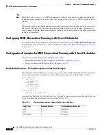
Table 22-1
lists the maximum latency requirements for various interface speeds.
Priority Propagation with Imposed Burstiness
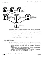
A single physical interface can have large numbers of logical interfaces and each of these logical
interfaces can have both priority and nonpriority traffic competing for the physical link. To minimize
latency, the priority traffic of one logical interface has priority over the nonpriority traffic of other logical
interfaces, thereby imposing burstiness on the minimum rate traffic of other logical interfaces. The
latency that the priority traffic incurs results from the rate constraining the delivered rate of the priority
traffic. In many cases, this constraining rate is not the rate of the priority class’s parent policy.
For example, suppose a 10 Gigabit Ethernet (GE) interface has 100 VLANs that are shaped to various
rates. Each VLAN has a priority class and additional classes configured. Through priority propagation,
the scheduler delivers latency to the priority traffic based on the 10 GE rate and not the VLAN rate.
Table 22-1
Maximum Latency Requirements
Interface Speed
Maximum Latency
Greater than 2 Mbps
2 MTU + 6 ms
2 Mbps to 1 Gbps
2 MTU
1 Gbps or greater
1 ms


