VCC-5CL1R
Rev. 905-0022-02
©2015 CIS Corporation. All rights reserved.
8
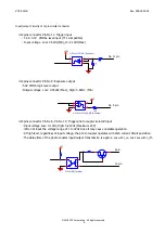
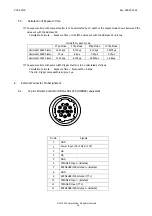
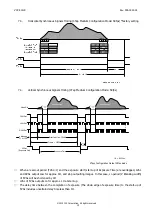
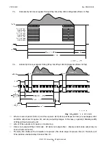
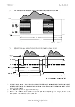
Input/output Circuitry of 12pin circular connector
◇
12pins connector Pin No 11: Trigger input
・
5.0V
、
3.3V
CMOSL level input (TTL compatible)
・
Input voltage
Low: 0.5Vdc(Min), Hi: 2.1Vdc(Max)
HD74LV1GT14A (Renesas)
1
2
3
5
4
100
1K
+5.0V
◇
12pins connector Pin No 9: Exposure output
・
5.0V CMOS logic level output
・
Output voltage
Low: 0.55Vdc (Max), High: 3.8Vdc
(Min)
+5.0V
HD74LV1GT32ACME (Renesas)
1
2
3
4
5
100
◇
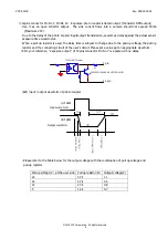
12pins connector Pin No 6, Pin No 10: Trigger photo coupler isolated input
・
Input voltage Low: 0-1Vdc, High: 3-24Vdc (Maximum 24V)
※
Do not input the voltage range of 1 to 3Vdc since it may cause unstable operation.
・
At high level, regardless of input voltage, the photo coupler operates with 4mA current circuit and drive.
・
The delay time of the photo coupler input/output transmission is approx.
5
μ
s with t_on, and 35
μ
s with t_off
.
G
D
S
TLP291SE (Toshiba)
VCC
6 pin
10 pin
No. 11 pin
No. 9 pin


