background image

VCC-5CL1R 


   Rev. 905-0022-02 


©2015 CIS Corporation. All rights reserved. 


Table of Contents 


                                                                                                                PAGE 

1.


Scope of Application .............................................................................................................................................. 3


2.


Handling Precautions ............................................................................................................................................. 3


3.


Product Outline ..................................................................................................................................................... 4


4.


Specification .......................................................................................................................................................... 5


4.1.


General Specification .................................................................................................................................. 5


4.2.


Camera Input/Output Signals Specification .................................................................................................. 7


4.3.


Spectral response ..................................................................................................................................... 10


4.4.


Video Output Format ................................................................................................................................ 10


5.


Camera Function Settings ..................................................................................................................................... 12


5.1.


Note for Functions .................................................................................................................................... 14


5.2.


Table for Preset Shutter Value ................................................................................................................... 14


5.3.


Calculation of Exposure Time .................................................................................................................... 16


6.


External Connector Pin Assignment ....................................................................................................................... 16


6.1.


12 pins Circular Connector HR10-10R-12PA (HIROSE) equivalent ................................................................. 16


6.2.


Camera Link Connector


12226-1100-00PL (SUMITOMO 3M) ....................................................................... 17


6.3.


PoCL/CL


Selection Switch ......................................................................................................................... 17


6.4.


LED Indicator (DC IN) ............................................................................................................................... 17


7.


Timing Diagram ................................................................................................................................................... 18


7.1.


Horizontal Synchronous Signals Timing (2Tap Base Configuration Mode: 30fps) ........................................... 18


7.2.


Vertical Synchronous Signals Timing (2Tap Base Configuration Mode: 30fps) ............................................... 18


7.3.


Horizontal Synchronous Signals Timing (4Tap Medium Configuration Mode: 59fps)


*factory setting ............... 19


7.4.


Vertical Synchronous Signals Timing (4Tap Medium Configuration Mode: 59fps) ........................................... 19


7.5.


Horizontal Synchronous Signals Timing (8Tap Full, 8Tap 10bit Configuration Mode: 117fps) ......................... 20


7.6.


Vertical Synchronous Signals Timing (8Tap Full, 8Tap 10bit Configuration Mode: 117fps) ............................. 20


7.7.


Horizontal Synchronous Signals Timing (10Tap 8bit Configuration Mode: 140fps) .........................................  21


7.8.


Vertical Synchronous Signals Timing (10Tap 8bit Configuration Mode: 140fps) ............................................. 21


7.9.


Fixed Trigger Shutter Mode ....................................................................................................................... 22


7.10.


Pulse Width Trigger Shutter Mode .............................................................................................................. 23


8.


Shading Correction .............................................................................................................................................. 24


8.1.


Shading Detection .................................................................................................................................... 24


9.


Vertical Partial Scan Mode .................................................................................................................................... 25


10.


Horizontal Partial Mode (Selection of Horizontal Pixel Number) ............................................................................... 26


11.


Binning Mode ...................................................................................................................................................... 27


12.


Serial Communication Function ............................................................................................................................. 28


13.


Sequence Control Function ................................................................................................................................... 30


13.1.


Auto mode ............................................................................................................................................... 31


13.2.


CC mode .................................................................................................................................................. 32


13.3.


Precaution and Instruction ........................................................................................................................ 33


14.


Factory Settings ................................................................................................................................................... 34


15.


CMOS Optical Axis Accuracy ................................................................................................................................. 35


16.


Dimensions ......................................................................................................................................................... 36


17.


Cases for Indemnity (Limited Warranty) ................................................................................................................ 37


18.


CMOS Pixel Defect ............................................................................................................................................... 37
 

Содержание VCC-5CL1R

Страница 1: ...VCC 5CL1R Rev 905 0022 02 2015 CIS Corporation All rights reserved Camera Link I F 5 2M Pixels CMOS Color RAW Camera VCC 5CL1R Product Specifications Operational Manual CIS Corporation English...

Страница 2: ...3 Horizontal Synchronous Signals Timing 4Tap Medium Configuration Mode 59fps factory setting 19 7 4 Vertical Synchronous Signals Timing 4Tap Medium Configuration Mode 59fps 19 7 5 Horizontal Synchrono...

Страница 3: ...VCC 5CL1R Rev 905 0022 02 2015 CIS Corporation All rights reserved 2 19 Product Support 37 20 Ordering Information 37 21 T License 37...

Страница 4: ...e force or static electricity that could damage the camera z Do not shoot direct images that are extremely bright e g light source sun etc and when camera is not in use put the lens cap on z Follow th...

Страница 5: ...se width trigger shutter mode Full frame rates and video output format are as follows One push White Balance Shading correction Sequence control Optional Accessories M42 to C conversion ring M42 to F...

Страница 6: ...0bit Configuration 5 Resolution 2048 TV Lines 6 Output Format Sensor ADC 12bit Camera Link output 8bit 10bit 12bit 8bit 10bit at 8Tap mode 8bit at 10Tap mode Raw output 7 Sensitivity F4 2000lx shutter...

Страница 7: ...urability Vibration Acceleration 98m s2 10G Frequency 20 200 Hz Direction X Y and Z 3 directions Testing time 120min for each direction Shock No malfunction shall occur with 980m s2 100G for X Y and Z...

Страница 8: ...Negative selectable Pulse Width 3 s 2 frames Functionally no upper limitation is set but at long time exposure the increase of noises and the decrease of setup level and white clip level could happen...

Страница 9: ...utput voltage Low 0 55Vdc Max High 3 8Vdc Min 5 0V HD74LV1GT32ACME Renesas 1 2 3 4 5 100 12pins connector Pin No 6 Pin No 10 Trigger photo coupler isolated input Input voltage Low 0 1Vdc High 3 24Vdc...

Страница 10: ...e pull up resistor and the connecting circuit of the user s circuit Please set a value get an appropriate waveform For your reference exposure output of 12pins connector Pin No 7 is a pulse with no de...

Страница 11: ...e 2560pixel G R G R 1 2 3 4 4 3 Spectral response Lens characteristics and illuminant characteristics are not considered 4 4 Video Output Format Bayer Pattern GRBG Bayer Pattern will also be reversed...

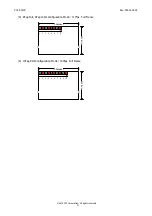
Страница 12: ...All rights reserved 11 2048 Line 2560pixel G R G R G R G R 1 2 3 4 5 6 7 8 2048 Line 2560pixel G R G R G R G R 1 2 3 4 5 6 7 8 G R 9 10 3 8Tap Full 8Tap 10bit Configuration Mode 117fps Full Frame 4 1...

Страница 13: ...SURE isolated 9pin EXPOSURE TTL 1 7pin FVAL isolated 9pin EXPOSURE TTL 2 7pin EXPOSURE isolated 9pin FVAL TTL 3 7pin FVAL isolated 9pin FVAL TTL Cursor Display 8 0 OFF 1 ON Cursor X Coordinate 9 0 255...

Страница 14: ...es set with the Addresses 50 51 and 52 are reflected first then ON Horizontal Partial Mode Selection of horizontal pixel numbers 55 0 Horizontal 2560 Pixels 1 Horizontal 2048 Pixels 2 Horizontal 1920...

Страница 15: ...Up Function up to 18dB However image degradation is inevitable when gain is set close to 18dB We recommend evaluating it first Please be noted that maximum 6 seconds shall be waited after turning its...

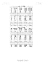
Страница 16: ...000 1 19000 1 19000 1 19000 13 1 31000 1 31000 1 31000 1 29000 14 1 51000 1 51000 1 61000 1 57000 15 1 51000 1 76000 1 101000 1 106000 1920pixels 2048Lines Data 2Taps Mode 4Taps Mode 8Taps Mode 10Taps...

Страница 17: ...125 s 3 4375 s Horizontal 2048 Pixels 13 s 6 5 s 3 25 s 2 75 s Horizontal 1920 Pixels 12 125 s 6 125 s 3 0833 s 2 583 s The exposure time with pulse width trigger shutter is to be calculated as follow...

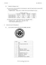
Страница 18: ...2 cable Lighting Power supply via both CL1 cable and CL2 cable Since the required current exceeds the tolerable range of one PoCL cable please make sure to supply power via two cables Connector CL1 Co...

Страница 19: ...0fps When a read out period FVAL 1 and the exposure start start up of Exposure Time are overlapped LVAL and DVAL output Low for approx 4H and stop outputting images In this case Lo period V Blanking w...

Страница 20: ...Time SP Out Exposure Out 2 0 4 8 2 0 4 8 1 1 1H 8 125us Video Out Effective Line 2048H 7 9H Effective Line Invalid Line Effective Line Invalid Line When a read out period FVAL 1 and the exposure star...

Страница 21: ...rt up of Exposure Time are overlapped LVAL and DVAL output Low for approx 4H and stop outputting images In this case Lo period V Blanking width of FVAL will be shortened by 4H LVAL of FVAL outputs Lo...

Страница 22: ...s When a read out period FVAL 1 and the exposure start start up of Exposure Time are overlapped LVAL outputs Low for approx 4H and stop outputting images In this case Lo period V Blanking width of FVA...

Страница 23: ...synchronous loading The actual exposure period is longer by approx 1 s at the front and approx 8 s at the end as shown below The min setting value of Fixed Trigger Shutter Mode is 1H min It depends on...

Страница 24: ...pixels 37 s 19 s 9 s 8 s The value for 2x2 binning and 4x4 binning are the same as the one for horizontal 2560 pixels With the above Exposure Time Delay and several dozen ns of jitter occur due to asy...

Страница 25: ...data first then turn the shading correction ON address 43 to execute this function 8 1 Shading Detection Shoot a uniform object such as a pattern box to full screen then turn shading detection ON addr...

Страница 26: ...73 29 9 fps 59 4 fps 116 9 fps 140 3 fps Setting Examples in case of Horizontal 2048 1920 pixels Horizontal x Vertical Effective Entire frame Frame Rate Entire frame lines fps Lines H Lines H 2Tap Mod...

Страница 27: ...ed at Horizontal Partial mode This mode is applicable along with Vertical Partial mode The horizontal pixel number is 2050 pixels at 10tap 2048 pixels mode The last 2 pixels are dummy pixels 2048 Line...

Страница 28: ...ts faster and exposure time becomes 1 2 Not applicable in conjunction with Horizontal Partial mode and Vertical Partial mode 4x4 binning Four by four pixels for each color pixel are mixed and are outp...

Страница 29: ...5 Function settings 3 How to set a Command Input a command in capital letters Separate between a command and a parameter by one space From the head of input character to the linefeed code r or n is an...

Страница 30: ...value r n Linefeed Returned value sp Prompt Space 5 r or n Make sure to input to indicate the end of the command 6 Initial settings Input INIT to return to the factory settings Data are not saved at...

Страница 31: ...There are two control modes Auto mode and CC mode When using Sequence Control function the following operational modes shall be set in advance Trigger Shutter Mode Fixed Shutter Mode or Pulse Width Tr...

Страница 32: ...each Index and the number of the Index to be used can be set Whenever a trigger is input the Index moves and the parameter set values are applied to the camera Auto Mode Flow Chart Sequence Index repe...

Страница 33: ...3 and CC4 signals Whenever a trigger is input the Index specified by the CC signal is selected and the corresponding parameter set values are applied to the camera CC Mode Flow Chart Input Output CC4...

Страница 34: ...rizontal starting position can be set per 64 pixels However it should be within the range which can be indicated Exposure time shall be more than 80 s in sequence mode The minimum trigger interval is...

Страница 35: ...e TTL Cursor Display 8 0 OFF Horizontal Flip 11 0 Normal Defective Pixel Correction 13 1 ON Defective pixels found at ex factory are corrected Gain 20 0 0dB Shutter 23 0 Preset shutter off White Balan...

Страница 36: ...VCC 5CL1R Rev 905 0022 02 2015 CIS Corporation All rights reserved 35 15 CMOS Optical Axis Accuracy...

Страница 37: ...VCC 5CL1R Rev 905 0022 02 2015 CIS Corporation All rights reserved 36 16 Dimensions...

Страница 38: ...amage or losses are caused by malfunction or other problems resulting from use of equipment or software that is not specified z In case damage or losses are caused by repair or modification conducted...

Отзывы: