5
Device Details
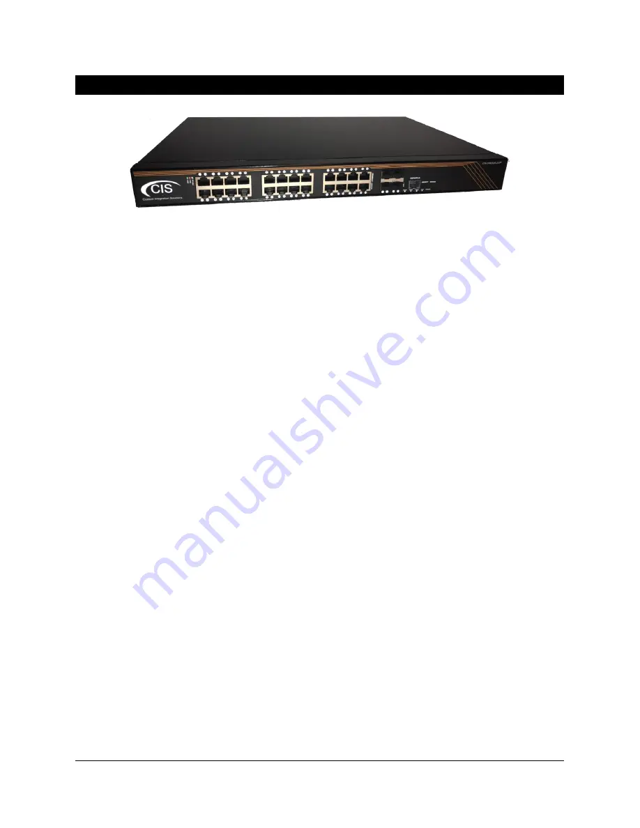
Ports
•
24 Gigabit Ethernet ports (With Auto MDI/X
—
You can use straight-through or cross-over cables
for connecting devices to the switch).
•
4 SFP+ cages, which accept both 1.25 Gb SFP and 10 Gb SFP+ modules.
•
RJ45 serial port
—
disabled by default.
LED Indicators
•
PWR LED - lit when the switch is powered on.
•
USR LED - an LED that can be customized to display different information.
•
The top row LEDs indicate PoE out status. A green LED indicates that the respective port uses low
voltage, a red LED indicates high voltage.
o
A flashing
green
LED - indicates a problem with a low voltage device.
o
A flashing
red
LED - indicates a problem with a high voltage device.
•
The bottom row LEDs indicate Ethernet and SFP port activity.
•
FAN FAULT LED - indicates a problem with the cooling fans.
•
PoE FAULT LED - indicates the switch has exceeded the overall maximum PoE output limit. Port
PoE-out priorities work in 3 independent sections (8 ports each) and an overload will occur in
any section that breaches 150 watts of consumption.
Buttons
Reset button: This button is located on the side next to the USB port. Hold this button while the device is
powered off, then apply power. Keeping holding until the USR LED light starts flashing, (5 seconds) then
release the button to reset to the default CIS configuration. You can use this procedure if you have
forgotten the password to access the device, or simply wish to return the unit to its default configuration
state.
Input Power Requirements
Supported input voltage-100V AC-240V AC.
Содержание CRS328-24P
Страница 1: ...CIS CRS328 24P User Manual...


