– 13 –
7. DIODE TEST
WARNING:
NEVER CONNECT THE TEST LEAD TO ANY VOLTAGE WHEN THE FUNCTION
SWITCH IS SET TO
/
. REMOVE ALL POWER FROM THE CIRCUIT BEING TESTED WHEN
PERFORMING THE DIODE TEST. DISCHARGE ANY CHARGED CAPACITORS.
Note: If the diode is part of a circuit, it is necessary to discon-
nect one end of the diode to avoid any unwanted interference
from the rest of the circuit. The value indicated in the display
during the diode check is the forward bias voltage.
➔
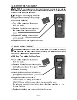
Set the function switch to
/
.
➔
The LED next to V/ /F/ / jack
will turn on.
➔
Plug the red test lead into
V/ /F/ / jack and the black
test lead into
jack.
➔
Apply the test leads across the
diode terminals and note the
meter reading.
➔
Reverse the diode and note this
reading. Based on the reading
the result can be evaluated as
follows:
– If one reading is around 0.5
and the other reading is ʻIʼ,
the diode is good
– If both readings are ʻIʼ, the
diode is open (defective)
– If both readings are very
small or 0 (zero), the diode is
shorted (defective)
CAP
CIRCUIT-TEST
DMR-4200
20A
TEMP
mA
HOLD
POWER
CAT II 1000V
V/Ω/F/ /
COM
D
C
V
O
LT
S
OHMS
Ω
C
A
PA
C
IT
A
N
CE
AC
V
O
LT
S
AC AMPS
D
C A
M
PS
TEMP F
REQ
CAP
CIRCUIT-TEST
DMR-4200
20A
TEMP
mA
HOLD
POWER
CAT II 1000V
V/Ω/F/ /
COM
D
C
V
O
LT
S
OHMS
Ω
C
A
PA
C
IT
A
N
CE
AC
V
O
LT
S
AC AMPS
D
C A
M
PS
TEMP F
REQ
Содержание DMR-4200
Страница 1: ...USER S MANUAL DIGITAL MULTIMETER DMR 4200 CIRCUIT TEST ELECTRONICS www circuittest com...
Страница 2: ......

