– 12 –
➔
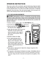
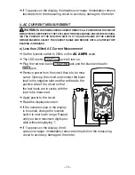
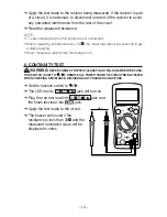
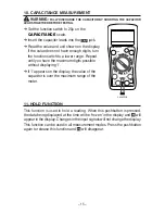
Apply the test leads to the resistor being measured. If the resistor is part
of a circuit, it is necessary to disconnect one end of the resistor to avoid
any unwanted interference from the rest of the circuit.
➔
Read the displayed resistance.
NOTE:
• ‘I’ is also displayed when the inputs are not connected.
• When measuring resistance above 1M , the meter may take a few seconds to get
a stable reading.
• Never measure a resistor that has voltage on it.
6. CONTINUITY TEST
WARNING:
NEVER CONNECT THE TEST LEADS TO ANY VOLTAGE WHEN THE FUNC-
TION SWITCH IS SET TO
/
. REMOVE ALL POWER FROM THE CIRCUIT BEING TESTED
WHEN CHECKING RESISTANCE. DISCHARGE ANY CHARGED CAPACITORS.
➔
Set the function switch to
/
.
➔
The LED next to V/ /F/ / jack will turn on.
➔
Plug the red test lead into V/ /F/ / jack and
the black test lead into
jack.
➔
Apply the test leads to the circuit.
➔
The buzzer will sound if the
resistance is less than 30 and the
measured resistance value will be
displayed in ohms.
CAP
CIRCUIT-TEST
DMR-4200
20A
TEMP
mA
HOLD
POWER
CAT II 1000V
V/Ω/F/ /
COM
D
C
V
O
LT
S
OHMS
Ω
C
A
PA
C
IT
A
N
CE
AC
V
O
LT
S
AC AMPS
D
C A
M
PS
TEMP F
REQ
WIRE
Содержание DMR-4200
Страница 1: ...USER S MANUAL DIGITAL MULTIMETER DMR 4200 CIRCUIT TEST ELECTRONICS www circuittest com...
Страница 2: ......

