


CO
-
100/P1001
Series | User Manual
79
5.2 Digital I/O (DIO) Hardware Specification
⚫
XCOM+: Isolated power in V+
⚫
XCOM-: Isolated power in V-
⚫
Isolated power in DC voltage: 9-30V
⚫
4x Digital Input (Source Type)
⚫
Input Signal Voltage Level
-
Signal Logic 0: XCOM+ = 9V,
Signal Low
-
V-
< 1V
XCOM+ > 9V,
V+
-
Signal Low
> 8V
-
Signal Logic 1: >
XCOM+
-
3V
⚫
Input Driving Sink Current:
-
Minimal: 1 mA
-
Normal: 5 mA
⚫
4x Digital Output (Open Drain)
-
DO Signal have to pull up resistor to XCOM+ for external device, the
resistance will affect the pull up current
-
Signal High Level: Pull up resistor to XCOM+
-
Signal Low Level: = XCOM-
-
Sink Current: 1A (Max)
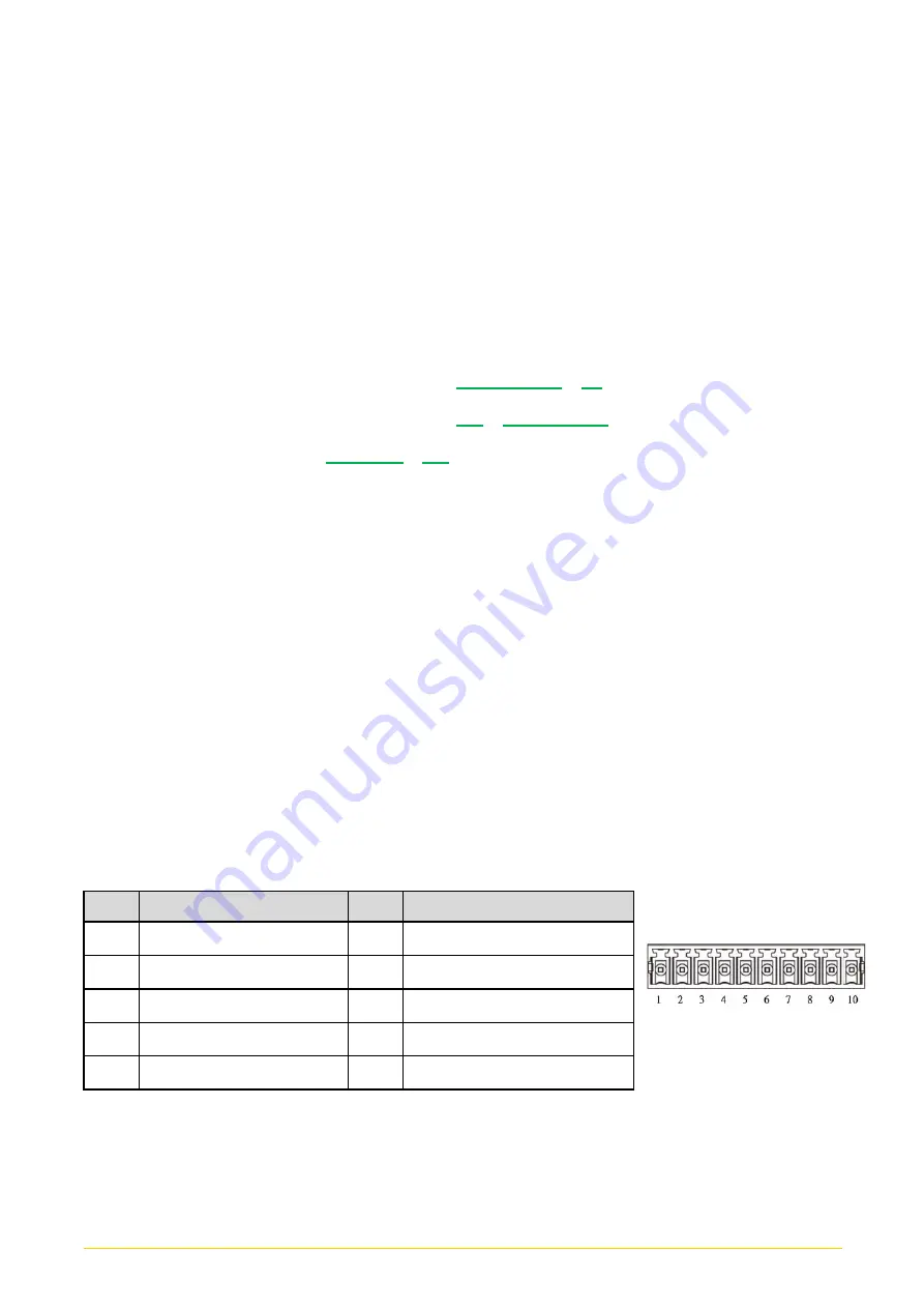
DIO1: Digital Input / Output Connector
Connector Type: Terminal Block 1X10 10-pin, 3.5mm pitch
Pin
Definition
Pin
Definition
1
DC INPUT
6
DO1
2
DI1
7
DO2
3
DI2
8
DO3
4
DI3
9
DO4
5
DI4
10
GND
Содержание CO-100/P1001 Series
Страница 11: ...CO 100 P1001 Series User Manual 11 Chapter 1 Product Introductions ...
Страница 17: ...CO 100 P1001 Series User Manual 17 Dimension CO W121C P1001 Unit mm CO W121C P1001E Unit mm ...
Страница 20: ...CO 100 P1001 Series User Manual 20 Chapter 2 Jumpers Switches Connectors ...
Страница 22: ...CO 100 P1001 Series User Manual 22 2 2 2 Bottom View ...
Страница 31: ...CO 100 P1001 Series User Manual 31 Chapter 3 System Setup ...
Страница 53: ...CO 100 P1001 Series User Manual 53 Chapter 4 BIOS Setup ...
Страница 72: ...CO 100 P1001 Series User Manual 72 Chapter 5 Product Application ...
Страница 80: ...CO 100 P1001 Series User Manual 80 ...
Страница 81: ...CO 100 P1001 Series User Manual 81 Chapter 6 Optional Accessories ...
Страница 83: ...CO 100 P1001 Series User Manual 83 ...
Страница 84: ...CO 100 P1001 Series User Manual 84 2 Fasten the VESA mount screws to complete the VESA mounting ...


