


CO
-
100/P1001
Series | User Manual
25
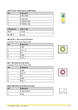
RESET1: Reset Switch
Switch
Definition
Push
Reset System
2.6 Definition of Connectors
CFAST1: CFast Connector
Pin
Definition
Pin
Definition
Pin
Definition
S1
GND
PC1
NC
PC10
NC
S2
S PC2
GND
PC11
NC
S3
SATA_TX2-
PC3
NC
PC12
NC
S4
GND
PC4
NC
PC13
+3.3V
S5
SATA_RX2- PC5
NC
PC14
+3.3V
S6
S PC6
NC
PC15
GND
S7
GND
PC7
GND
PC16
GND
PC8
NC
PC17
NC
PC9
NC
COM1~COM2: RS232 / RS422 / RS485 Connector
Connector Type: 9-pin D-Sub
Pin
RS232
Definition
RS422 / 485
Full Duplex
Definition
RS485
Half Duplex
Definition
1
DCD
TX-
DATA -
2
RXD
TX+
DATA +
3
TXD
RX+
4
DTR
RX-
5
GND
6
DSR
7
RTS
8
CTS
9
RI
Содержание CO-100/P1001 Series
Страница 11: ...CO 100 P1001 Series User Manual 11 Chapter 1 Product Introductions ...
Страница 17: ...CO 100 P1001 Series User Manual 17 Dimension CO W121C P1001 Unit mm CO W121C P1001E Unit mm ...
Страница 20: ...CO 100 P1001 Series User Manual 20 Chapter 2 Jumpers Switches Connectors ...
Страница 22: ...CO 100 P1001 Series User Manual 22 2 2 2 Bottom View ...
Страница 31: ...CO 100 P1001 Series User Manual 31 Chapter 3 System Setup ...
Страница 53: ...CO 100 P1001 Series User Manual 53 Chapter 4 BIOS Setup ...
Страница 72: ...CO 100 P1001 Series User Manual 72 Chapter 5 Product Application ...
Страница 80: ...CO 100 P1001 Series User Manual 80 ...
Страница 81: ...CO 100 P1001 Series User Manual 81 Chapter 6 Optional Accessories ...
Страница 83: ...CO 100 P1001 Series User Manual 83 ...
Страница 84: ...CO 100 P1001 Series User Manual 84 2 Fasten the VESA mount screws to complete the VESA mounting ...


