


CO
-
100/P1001
Series | User Manual
44
2.
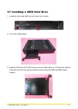
Fasten the screws from the rack’s front side. Please prepare 12 x M4 screws for fixing
the module through the
screw holes
as shown below.
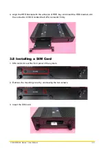
User can also prepare 16 x M4 screws for fixing the module through the
oblong holes
as
shown below.
The round screw holes have threads, while the oblong holes do
not have threads. Please select the screw-fixing hole position
according to the on-site environment.
NO
T
E
Содержание CO-100/P1001 Series
Страница 11: ...CO 100 P1001 Series User Manual 11 Chapter 1 Product Introductions ...
Страница 17: ...CO 100 P1001 Series User Manual 17 Dimension CO W121C P1001 Unit mm CO W121C P1001E Unit mm ...
Страница 20: ...CO 100 P1001 Series User Manual 20 Chapter 2 Jumpers Switches Connectors ...
Страница 22: ...CO 100 P1001 Series User Manual 22 2 2 2 Bottom View ...
Страница 31: ...CO 100 P1001 Series User Manual 31 Chapter 3 System Setup ...
Страница 53: ...CO 100 P1001 Series User Manual 53 Chapter 4 BIOS Setup ...
Страница 72: ...CO 100 P1001 Series User Manual 72 Chapter 5 Product Application ...
Страница 80: ...CO 100 P1001 Series User Manual 80 ...
Страница 81: ...CO 100 P1001 Series User Manual 81 Chapter 6 Optional Accessories ...
Страница 83: ...CO 100 P1001 Series User Manual 83 ...
Страница 84: ...CO 100 P1001 Series User Manual 84 2 Fasten the VESA mount screws to complete the VESA mounting ...


