CI-340 Operation Manual rev. 6/7/2017
CID Bio-Science
1554 NE 3
rd
Ave
Camas, WA 98607, USA
Phone: +1 (360) 833-8835
Fax: +1 (360) 833-1914
[email protected]
www.cid-inc.com
3
Technical Information
The CI-340 is a highly technologically advanced photosynthesis system. It contains a pump along with a
mass airflow sensor. A built-in microprocessor regulates the airflow rate, which is set by the user.
Specifically, the CI-340 is a non-dispersive IRGA in which the infrared light is shone through the gas in
the sampling chamber and then focused on a detector. The energy received at the detector is the total
energy entering the system minus the energy absorbed by the CO
2
in the sampling chamber. A
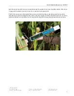
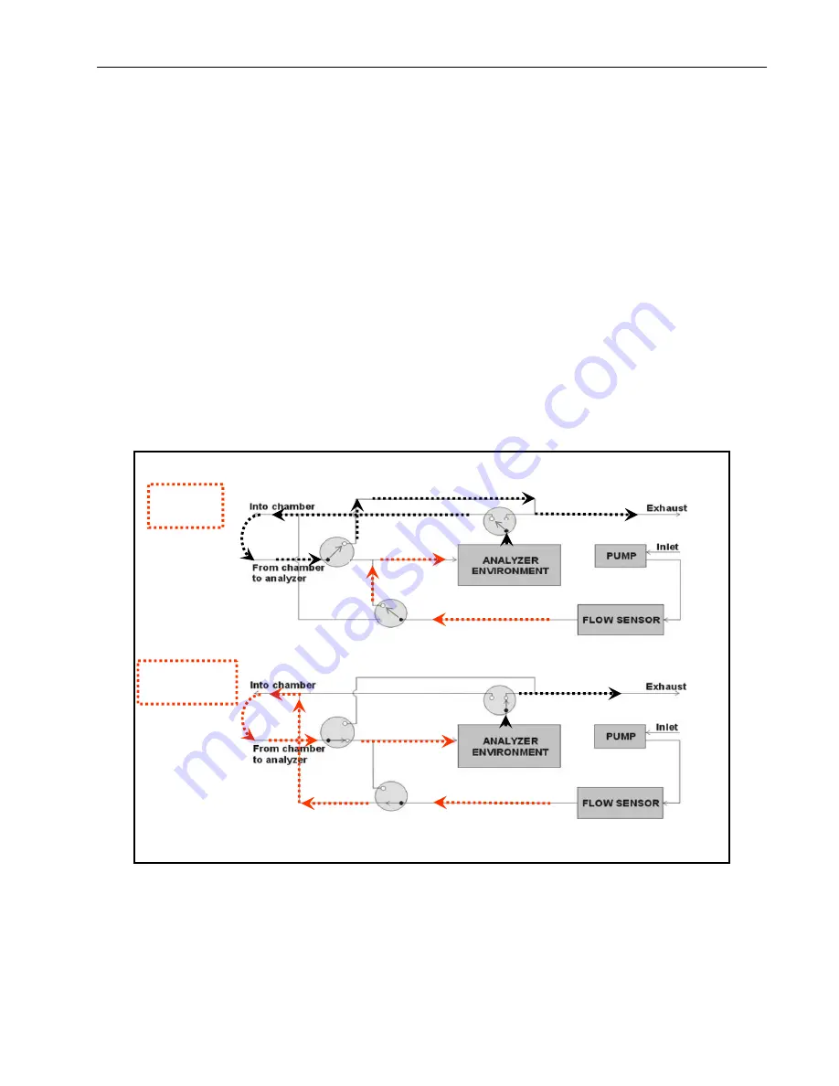
technical diagram (Figure 1) illustrates a flow chart for this instrument. An illustration of the CI-340
can be found in Figure 2.
The measurement process starts with the gas or air sample passing a solid-state CO
2
analyzer. The
output of the analyzer is amplified, sampled by an analog-to-digital (A-D) converter, and sent to the
microprocessor. The processor averages these readings and corrects them for any non-linearity
present in the analyzer. A relative value of CO
2
concentration is continually updated by the
microprocessor. Each reading reflects a sample being taken every second during a specified time
period. This can be determined by setting the time interval. The rate at which samples are saved in
memory is determined by the “sampling rate” or the time interval input at the beginning of each
measurement session. If you listen carefully during analysis, you can hear the valves switching from
reading the “in” values to the “out” values and the sample number or count will increase by one.
Inlet
Outlet
Figure 1: The pathway of airflow through the CI-340 during measurement. The top figure illustrates
the valve placement and air flow during an “in” reading and the lower
figure illustrates the valve
placement and air flow during and “out” reading.
Содержание CI-340
Страница 3: ......


