


7 - LGN UNIT CONNECTIONS
7.1 - Recommendations for the installation
of liquid chillers with remote condenser.
LGN units (split units to connect to air-cooled condensers) have
been specially designed to optimise the operation of split
installations using air-cooled condensers as a cooler heat
rejection system.
The cooling installation of an operational system is therefore
limited to connect the LGN unit air-cooled condenser inlet and
outlet.
Components such as the check valve (on the discharge line),
liquid sight glass, solenoid valves are fitted and factory wired.
The drier is provided with the unit and must be installed upstream
of the solenoid valve on the liquid line
The Pro- LGN control integrates logics allowing the
different fixed and variable speed fan variants to be controlled.
To ensure optimum and reliable performance of the units, it is
necessary to respect several regulations mentioned below when
these machines are connected to remote condensers:
-
Size the discharge and liquid line pipes according to the
recommendations in the following paragraphs (if required,
install a double riser column to ensure correct oil circulation
in the refrigerant circuit).
-
Select a condenser with an integrated subcooler to obtain a
minimum of 3 K subcooling at the expansion valve inlet.
-
Install the drier provided with the unit as close as possible to
the liquid line drier
-
Install the outside air temperature sensor provided near the
air-cooled condenser. For units with remote condenser control
(option 154), the sensor is provided. The outside air
temperature is vital in order for the entire system to run
smoothly.
For remote air-cooled condenser control (option 154):
-
Connect the fan stages electrically on the control panel using
the auxiliary electronic board "AUX 1". Refer to chapters 14
and 15 for the description of the analogue and discrete inputs
and outputs for assigning fan stages.
-
Make the communication BUS (twisted and shielded BUS
type communication cable RS485) between the specific
electronic AUX 1 board, that must be integrated in the
condenser control box, and the NRCP master board of the
Dynaciat LG unit.
-
Configuration in Pro- the number of fan stages and
fan type based on the air-cooled condenser used in the
installation. Use of a variable speed drive on the first fan stage
is recommended for low ambient temperatures at partial load
and for condensers with few fans.
It is essential to select an air-cooled condenser with
a subcooler. Generally, 8°C of subcooling is
recommended at the condenser outlet.
7.2 - Pipe routing and connection
On all units release the holding charge pressure before opening
the circuit.
Use different valves and/or remove the safety cap provided from
the conical Schraeder connections, press on the valve tip to
release all the standby charge in the system (nitrogen).
Preparation before debrazing the liquid and discharge plugs:
-
Remove all components that may be damaged during
debrazing procedures
-
Braze the pipes: Remove the conical Schrader connections
near the area, remove the pipe collars, remove the casing
panels and the metal crossbars.
-
These components must be replaced before start-up of the
system.
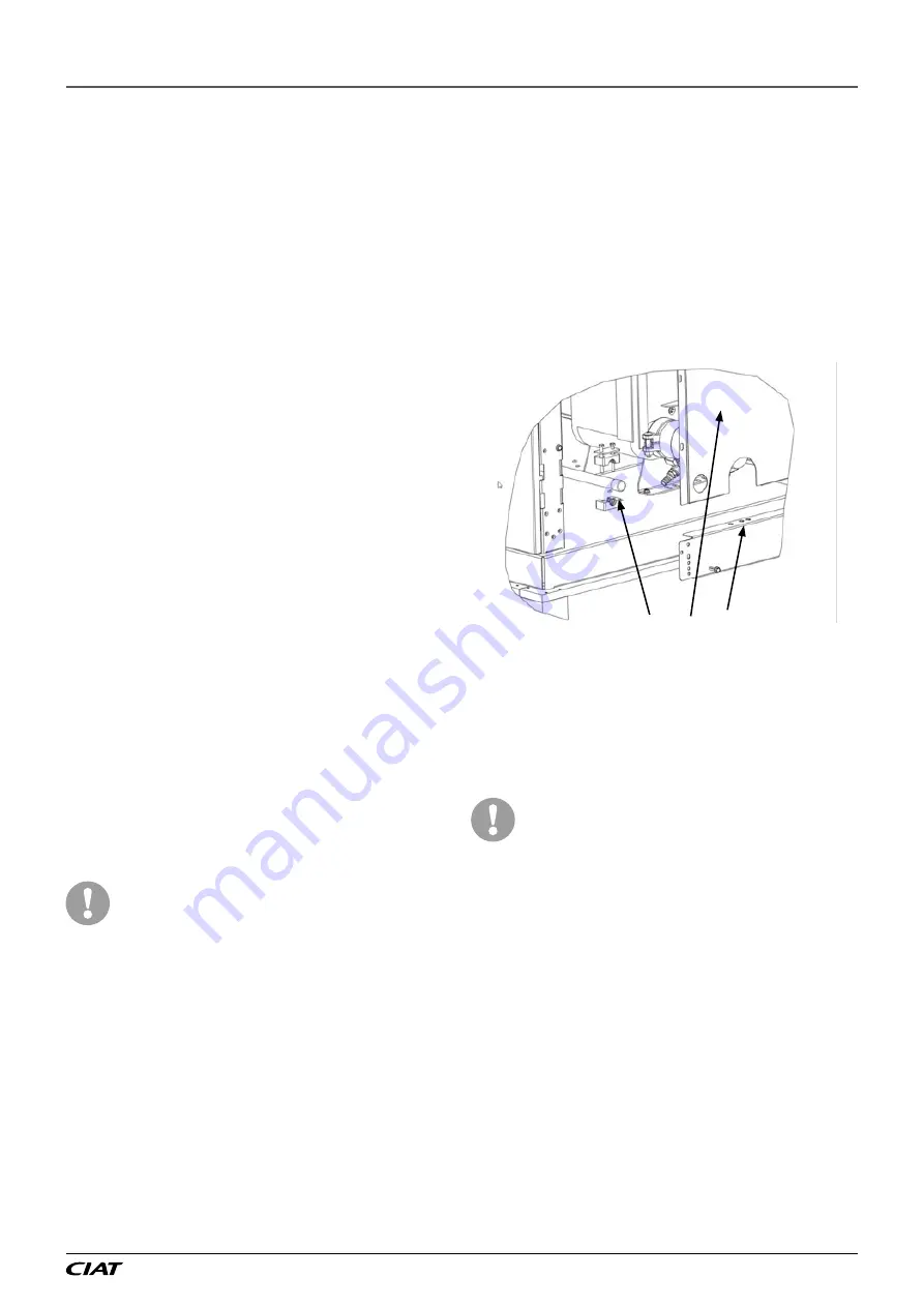
Components to remove for brazing
Unweld the caps and prepare the tubes for connection.
Connect the liquid line to the system, fit the drier upstream of
the unit
Make the high-pressure connections (discharge line) between
the unit and the condenser.
During these operations, allow an inert gas such as nitrogen to
circulate in the ducts to prevent the formation of copper oxide.
The condenser circuit routing must primarily
respect industry practices concerning the static
support and the thermal expansion of copper pipes.
To control vibration in the system, the collar
positions on the machine pipes must not be
changed. Clamps for securing the pipes are
provided at the refrigeration unit outlet. It is
essential that these clamps are tightened to prevent
vibrations and potential ruptures.
The pipes between the unit and the condenser must
be correctly supported, according to their size and
their operating weight. The pipes must be supported
in order to ensure that the vibration levels on the
pipes is lower than the existing values on the
compressor. If resonance occurs, reduce the range
between the collar until the vibration levels are
acceptable.
EN-39
Dynaciat LG/LGN
Содержание DYNACIAT LG 080
Страница 1: ...DYNACIAT LG LGN 07 2018 10188 Instruction manual...
Страница 2: ...Dynaciat LG LGN EN 2...
Страница 3: ...EN 3 Dynaciat LG LGN...
Страница 67: ...EN 67 Dynaciat LG LGN...


